Search Results: "tach"

28 May 2013

Russell Coker: SCSI Failures

For a long time it was widely regarded that SCSI was the interface for all serious drives that were suitable for Enterprise Use or for anything else which requires reliable operation. On the other hand IDE was for cheap disks that were only suitable for home use. The SCSI vs IDE issue continues to this day but now we have SAS and SATA filling the same market niches with the main difference between the current debate and the debate a decade ago being that a SATA disk can be connected on a SAS bus. Both SAS and SATA have a single data cable for each disk which avoids the master/slave configuration on IDE and the issue of bus device ID number (from 0-7 or 0-15) and termination on SCSI. Termination When a high speed electrical signal travels through a cable some portion of the signal will be reflected from any cable end point or any point of damage. To prevent the signal reflection from the end of a cable you can have a set of resistors (or some other terminating device) at the end of the cable, see the Terminator(electrical) Wikipedia page [1] for a brief overview. As an aside I think that page could do with some work, if you are an EE with a bit of spare time then improving that page would be a good thing. SCSI was always designed to have termination while IDE never was. I presume that this was largely due to the cable length (18 for IDE vs 1.5m to 25m for SCSI) and the number of devices (2 for IDE vs 7 or 15 for SCSI). I also presume that some of the problems that I ve had with IDE systems have been related to signal problems that could have been avoided with a terminated bus. My first encounter with SCSI was when working for a small business that focused on WindowsNT software development. Everyone in the office knew a reasonable amount about computers and was happy to adjust the hardware of their own workstation. A room full of people who didn t understand termination who fiddled with SCSI buses tended to give a bad result. On the up-side I learned that a SCSI bus can work most of the time if you have a terminator in the middle of the cable and a hard drive at the end. There have been two occasions when I ve been at ground zero for a large deployment of servers from a company I ll call Moon Computers. In both cases there were two particularly large and expensive servers in a cluster and one of the cluster servers had data loss from bad SCSI termination. This is particularly annoying as the terminators have different colours, all that was needed to get the servers working was to change the hardware to make them look the same. As an aside the company with no backups [2] had one of the servers with bad SCSI termination. Heat SCSI disks and now SAS disks tend to be designed for higher performance, this usually means greater heat dissipation. A disk that dissipates a lot of heat won t necessarily work well in a desktop case with small and quiet fans. This can become a big problem if you have workstations running 24*7 in a hot place (such as any Australian city that s not in Tasmania) and turn the air-conditioner off on the weekends. One of my clients lost a few disks before they determined that IDE disks are the only option for systems that are to survive Australian heat without any proper cooling. Differences between IDE/SATA and SCSI/SAS In 2009 I wrote about vibration and SATA performance [3]. Rumor has it that SCSI/SAS disks are designed to operate in environments where there is a lot of vibration (servers with lots of big fans and fast disks) while IDE/SATA disks are designed for desktop and laptop systems in quiet environments. One thing I d like to do is to test performance of SATA vs SAS disks in a server that vibrates. SCSI/SAS disks have apparently been designed for operation in a RAID array and therefore will give a faster timeout on a read error (so another disk can return the data). While IDE/SATA disks are designed for a non-RAID situation and will spend longer trying to read the data. There are also various claims about the error rates from SCSI/SAS disks being better than those of IDE/SATA disks. But I think that in all cases the error rates are small enough not to be a problem if you use a filesystem like ZFS or BTRFS but they are also large enough to be a significant risk with modern data volumes if you have a lesser filesystem. Data Loss from Storage Failure In the data loss that I ve personally observed from storage failures the loss from SCSI problems (termination and heat) is about equal to all the hardware related data loss I ve seen on IDE disks. Given that the majority of disks I ve been responsible for have been IDE and SATA that s a bad sign for SCSI use in practice. But all serious data loss that I ve seen has involved the use of a single disk (no RAID) and inadequate backups. So a basic RAID-1 or RAID-5 installation will solve most hardware related data loss problems. There was one occasion when heat caused two disks in a RAID-1 to give errors at the same time, but by reading from both disks I managed to get almost all the data back, RAID can save you from some extreme error conditions. That situation would have been ideal for BTRFS or ZFS to recover data. Conclusion SCSI and SAS are designed for servers, using them in non-server systems seems to be a bad idea. Using SATA disks in servers can have problems too, but not typically problems that involve massive data loss. Using technology that is too complex for the people who install it seems risky. That includes allowing programmers to plug SCSI disks into their workstations and whoever it was from Moon computers or their resellers who apparently couldn t properly terminate a SCSI bus. It seems that the biggest advantage of SAS over SCSI is that SAS is simple enough for most people to be able to correctly install it. Making servers similar to the systems that the system administrators use at home seems like a really good idea. I think that one of the biggest benefits of using x86 systems as servers is that skills learned on home PCs can be transferred to administration of servers. Of course it would also be a good idea to have test servers that are identical to servers in production so that the sysadmin team can practice and make mistakes on systems that aren t mission critical, but companies seem to regard that as a waste of money apparently the risk of down-time is cheaper.

23 May 2013

Steve Kemp: Lumail continues to progress

Although I've still not got the ability to reply to messages, and composing new ones is ugly, my toy mail client is working nicely. I've received a couple of patches, and given commit access to the repository to one other user. Currently I'm still juggling primitives around and working out what is missing. The big exceptions are the obvious: But on the plus side the lua scripting is lovely:
precious ~/git/lumail $ rm /tmp/unread.log
precious ~/git/lumail $ ./lumail  --rcfile ./lumail.lua --eval "dump_unread();"
precious ~/git/lumail $ head /tmp/unread.log
Selected folder /home/skx/Maildir/.Automated.backups
	Folder has 10 unread messages
Selected folder /home/skx/Maildir/.Automated.bounces
	Folder has 3 unread messages
Selected folder /home/skx/Maildir/.CRM.Spam
	Folder has 7 unread messages
Selected folder /home/skx/Maildir/.facebook.com
	Folder has 4 unread messages
..
The website needs some love, most notably a logo. And there are several reported bugs/todo-items I need to work through. Still for a toy program I'm using it daily. (Though still using mutt to reply to messages & view/save attachments.)

16 May 2013

Vincent Sanders: True art selects and paraphrases, but seldom gives a verbatim translation

In my professional life I am sometimes required to provide technical support to one of our salesmen. I find this an interesting change in pace though sometimes challenging.

Occasionally I fail to clearly convey the solution we are trying to sell because of my tendency to focus on detail the customer probably does not need to understand but I think is the interesting part of the problem.

Conversely sometimes the sales people gloss over important technology choices which have a deeper impact on the overall solution. I was recently in such a situation where as part of a larger project the subject of internationalisation (you can see why it gets abbreviated to i18n) was raised.

I had little direct personal experience with handling this within a project workflow so could not give any guidance but the salesman recommended the Transifex service as he had seen it used before, indicated integration was simple and we moved onto the next topic.

Unfortunately previous experience tells me that sometime in the near future someone is going to ask me hard technical questions about i18n and possibly how to integrate Transifex into their workflow (or at least give a good estimate on the work required).
LearningBeing an engineer I have few coping strategies available for situations when I do not know how something works. The approach I best know how to employ is to give myself a practical crash course and write up what I learned...so I did.

I proceeded to do all the usual things you do when approaching something unfamiliar (wikipedia, google, colleagues etc.) and got a basic understanding of internationalisation and localisation and how they fit together.

This enabled me to understand that the Transifex workflow proposed only covered the translation part of the problem and that, as Aldrich observed in my title quote, there is an awful lot more to translation than I suspected.
PlatformsMy research indicated that there are numerous translation platforms available for both open source and commercial projects and Transifex is one of many solutions.

Although the specific platform used was Transifex most of these observations apply to all these other platforms. The main lesson though is that all platforms are special snowflakes and once a project invests effort and time into one platform it will result in the dreaded lock in. The effort to move to another platform afterwards is at least as great as the initial implementation.

It became apparent to me that all of these services, regardless of their type, boil down to a very simple data structure. They appear to be a trivial table of Key:Language:Value wrapped in a selection of tools to perform format conversions and interfaces to manipulate the data.

There may be facilities to attach additional metadata to the table such as groupings for specific sets of keys (often referred to as resources) or translator hints to provide context but the fundamental operation is common.

The pseudo workflow is:
The first three steps are almost always performed together by the uploading of a resource file containing an initial set of translations in the "default" language and due to the world being the way it is this is almost always english (some services are so poorly tested with other defaults they fail if this is not the case!)

The platforms I looked at generally follow this pattern with a greater or lesser degree of freedom in what the keys are, how the groupings into resources are made and the languages that can be used. The most common issue with these platforms (especially open source ones) is that the input convertors will only accept a very limited number of formats and often restricted to just GNU gettext PO files. This means that to use those platforms a project would have to be able to convert any internal resources into gettext translatable format.

The prevalence of the PO format pushes assumptions into almost every platform I examined, mainly that a resource is for a single language translation and that the Key (msgid in gettext terms) is the untranslated default language string in the C locale.

The Transifex service does at least allow for the Key values to be arbitrary although the resources are separated by language.

Even assuming a project uses gettext PO files and UTF-8 character encoding (and please can we kill every other character encoding and move the whole world to UTF-8) the tools to integrate the import/export into the project must be written.

A project must decide some pretty important policies, including:
These are project policy decisions and, as I discovered, just as difficult to answer as the technical challenges.

Armed with my basic understanding it was time to move on and see how the transifex platform could be integrated into a real project workflow.
ImplementingProof of conceptMy first exercise was to take a trivial command line tool, use xgettext to generate a PO file and add the relevant libintl calls to produce gettext internationalised tool.

A transifex project was created and the english po file uploaded as the initial resource. A french language was added and the online editor used to provide translations for some strings. The PO resource file for french was exported and the tool executed with LANGUAGE=fr and the french translation seen.

This proved the trivial workflow was straightforward to implement. It also provided insight into the need to automate the process as the manual website operation would soon become exceptionally tedious and error prone.
Something more usefulTo get a better understanding of a real world workflow I needed a project that:
I selected the NetSurf web browser as it best fit this list.

Internally NetSurf keeps all the translated messages in a simple associative array this is serialised to an equally straightforward file named FatMessages. The file is UTF-8 encoded with keys separated from values by a colon. The Key is constrained to be ASCII characters with no colons and is structured as language.toolkit.identifier and is unique on identifier part alone.

This file is processed at build time into a simple identifier:value dictionary for each language and toolkit.

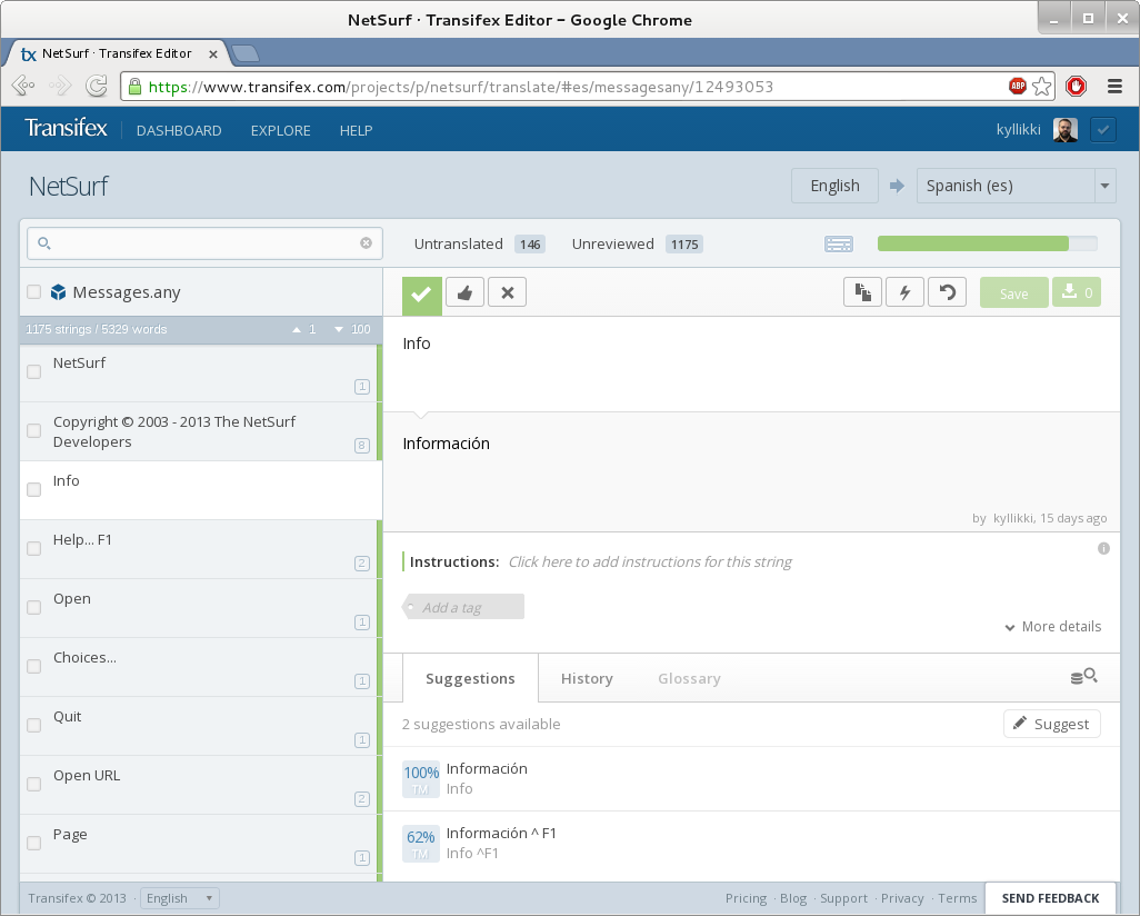
Transifex can import several resource formats similar to this, after experimenting with YAML and Android Resource format I immediately discovered a problem, the services import and export routines were somewhat buggy.

These routines coped ok with simple use cases but having more complex characters such as angle brackets and quotation marks in the translated strings would completely defeat the escaping mechanisms employed by both these formats (through entity escaping in android resource format XML is problematic anyway)

Finally the Java property file format was used (with UTF-8 encoding) which while having bugs in the import and export escaping these could at least be worked around. The existing tool that was used to process the FatMessages file was rewritten to cope with generating different output formats and a second tool to merge the java property format resources.

To create these two tools I enlisted the assistance of my colleague Vivek Dasmohapatra as his Perl language skills exceeded my own. He eventually managed to overcome the format translation issues and produce correct input and output.

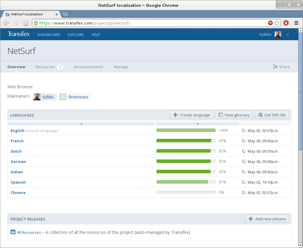
I used the Transifex platforms free open source product, created a new project and configured it for free machine translation from the Microsoft service, all of which is pretty clearly documented by Transifex.

Once this was done the messages file was split up tinto resources for the supported languages and uploaded to the transifex system.

I manually marked all the uploaded translations as "verified" and then added a few machine translations to a couple of languages. I also created spanish as a new language and machine translated most of the keys.

The resources for each language were then downloaded and merged and the resulting FatMessages file checked for differences and verified only the changes I expected appeared.

I quickly determined that manually downloading the language resources every time was not going to work with any form of automation, so I wrote a perl script to retrieve the resources automatically (might be useful for other projects too).

Once these tools were written and integrated into the build system I could finally make an evaluation as to how successful this exercise had been.
ConclusionsThe main things I learned from this investigation were:

Overall I think the final observation has to be that integrating translation services is not a straightforward operation and each project has unique challenges and requirements which reduce the existing platforms to compromise solutions.

9 May 2013

Benjamin Mako Hill: The Remixing Dilemma: The Trade-off Between Generativity and Originality

This post was written with Andr s Monroy-Hern ndez. It is a summary of a paper just published in American Behavioral Scientist. You can also read the full paper: The remixing dilemma: The trade-off between generativity and originality. It is part of a series of papers I have written with Monroy-Hern ndez using data from Scratch. You can find the others on my academic website.
Remixing the reworking and recombination of existing creative artifacts represents a widespread, important, and controversial form of social creativity online. Proponents of remix culture often speak of remixing in terms of rich ecosystems where creative works are novel and highly generative. However, examples like this can be difficult to find. Although there is a steady stream of media being shared freely on the web, only a tiny fraction of these projects are remixed even once. On top of this, many remixes are not very different from the works they are built upon. Why is some content more attractive to remixers? Why are some projects remixed in deeper and more transformative ways?
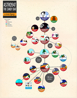
Remix Diagram
We try to shed light on both of these questions using data from Scratch a large online remixing community. Although we find support for several popular theories, we also present evidence in support of a persistent trade-off that has broad practical and theoretical implications. In what we call the remixing dilemma, we suggest that characteristics of projects that are associated with higher rates of remixing are also associated with simpler and less transformative types of derivatives.

Our study is focused on two interrelated research questions. First, we ask why some projects shared in remixing communities are more or less generative than others. Generativity a term we borrow from Jonathan Zittrain describes creative works that are likely to inspire follow-on work. Several scholars have offered suggestions for why some creative works might be more generative than others. We focus on three central theories:
  1. Projects that are moderately complicated are more generative. The free and open source software motto release early and release often suggests that simple projects will offer more obvious opportunities for contribution than more polished projects. That said, projects that are extremely simple (e.g., completely blank slates) may also uninspiring to would-be contributors.
  2. Projects by prominent creators are more generative. The reasoning for this claim comes from the suggestion that remixing can act as a form of cultural conversation and that the work of popular creators can act like a common medium or language.
  3. Projects that are remixes themselves are more generative. The reasoning for this final claim comes from the idea that remixing thrives through the accumulation of contributions from groups of people building on each other s work.
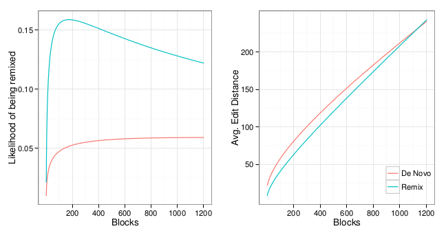
Our second question focuses on the originality of remixes and asks when more or less transformative remixing occurs. For example, highly generative projects may be less exciting if the projects produced based on them are all near-identical copies of antecedent projects. For a series of reasons including the fact that increased generativity might come by attracting less interested, skilled, or motivated individuals we suggest that each of the factors associated with generativity will also be associated with less original forms of remixing. We call this trade-off the remixing dilemma. We answer both of our research questions using a detailed dataset from Scratch, where young people build, share, and collaborate on interactive animations and video games. The community was built to support users of the Scratch programming environment, a desktop application with functionality similar to Flash created by the Lifelong Kindergarten Group at the MIT Media Lab. Scratch is designed to allow users to build projects by integrating images, music, sound, and other media with programming code. Scratch is used by more than a million users, most of them under 18 years old. To test our three theories about generativity, we measure whether or not, as well as how many times, Scratch projects were remixed in a dataset that includes every shared project. Although Scratch is designed as a remixing community, only around one tenth of all Scratch projects are ever remixed. Because more popular projects are remixed more frequently simply because of exposure, we control for the number of times each project is viewed. Our analysis shows at least some support for all three theories of generativity described above. (1) Projects with moderate amounts of code are remixed more often than either very simple or very complex projects. (2) Projects by more prominent creators are more generative. (3) Remixes are more likely to attract remixers than de novo projects. To test our theory that there is a trade-off between generativity and originality, we build a dataset that includes every Scratch remix and its antecedent. For each pair, we construct a measure of originality by comparing the remix to its antecedent and computing an edit distance (a concept we borrow from software engineering) to determine how much the projects differ. We find strong evidence of a trade-off: (1) Projects of moderate complexity are remixed more lightly than more complicated projects. (2) Projects by more prominent creators tend to be remixed in less transformative ways. (3) Cumulative remixing tends to be associated with shallower and less transformative derivatives. That said, our support for (1) is qualified in that we do not find evidence of the increased originality for the simplest projects as our theory predicted.
Two plots of estimated values for prototypical projects. Panel 1 (left) display predicted probabilities of being remixed. Panel 2 (right) display predicted edit distances. Both panels show predicted values for both remixes and de novo projects from 0 to 1,204 blocks (99th percentile).

Two plots of estimated values for prototypical projects. Panel 1 (left) displays predicted probabilities of being remixed. Panel 2 (right) displays predicted edit distances. Both panels show predicted values for both remixes and de novo projects from 0 to 1,204 blocks (99th percentile).

We feel that our results raise difficult but important challenges, especially for the designers of social media systems. For example, many social media sites track and display user prominence with leaderboards or lists of aggregate views. This technique may lead to increased generativity by emphasizing and highlighting creator prominence. That said, it may also lead to a decrease in originality of the remixes elicited. Our results regarding the relationship of complexity to generativity and originality of remixes suggest that supporting increased complexity, at least for most projects, may have fewer drawbacks. As supporters and advocates of remixing, we feel that although highly generative works that lead to highly original derivatives may be rare and difficult for system designers to support, understanding remixing dynamics and encouraging these rare projects remain a worthwhile and important goal. Benjamin Mako Hill, Massachusetts Institute of Technology
Andr s Monroy-Hern ndez, Microsoft Research
For more, see our full paper, The remixing dilemma: The trade-off between generativity and originality. Published in American Behavioral Scientist. 57-5, Pp. 643 663. (Official Link, Pay-Walled ).

7 May 2013

Matthew Garrett: A short introduction to TPMs

I've been working on TPMs lately. It turns out that they're moderately awful, but what's significantly more awful is basically all the existing documentation. So here's some of what I've learned, presented in the hope that it saves someone else some amount of misery.
What is a TPM?TPMs are devices that adhere to the Trusted Computing Group's Trusted Platform Module specification. They're typically microcontrollers[1] with a small amount of flash, and attached via either i2c (on embedded devices) or LPC[2] (on PCs). While designed for performing cryptographic tasks, TPMs are not cryptographic accelerators - in almost all situations, carrying out any TPM operations on the CPU instead would be massively faster[3]. So why use a TPM at all?
Keeping secrets with a TPMTPMs can encrypt and decrypt things. They're not terribly fast at doing so, but they have one significant benefit over doing it on the CPU - they can do it with keys that are tied to the TPM. All TPMs have something called a Storage Root Key (or SRK) that's generated when the TPM is initially configured. You can ask the TPM to generate a new keypair, and it'll do so, encrypt them with the SRK (or another key descended from the SRK) and hand it back to you. Other than the SRK (and another key called the Endorsement Key, which we'll get back to later), these keys aren't actually kept on the TPM - the running OS stores them on disk. If the OS wants to encrypt or decrypt something, it loads the key into the TPM and asks it to perform the desired operation. The TPM decrypts the key and then goes to work on the data. For small quantities of data, the secret can even be stored in the TPM's nvram rather than on disk.

All of this means that the keys are tied to a system, which is great for security. An attacker can't obtain the decrypted keys, even if they have a keylogger and full access to your filesystem. If I encrypt my laptop's drive and then encrypt the decryption key with the TPM, stealing my drive won't help even if you have my passphrase - any other TPM simply doesn't have the keys necessary to give you access.

That's fine for keys which are system specific, but what about keys that I might want to use on multiple systems, or keys that I want to carry on using when I need to replace my hardware? Keys can optionally be flagged as migratable, which makes it possible to export them from the TPM and import them to another TPM. This seems like it defeats most of the benefits, but there's a couple of features that improve security here. The first is that you need the TPM ownership password, which is something that's set during initial TPM setup and then not usually used afterwards. An attacker would need to obtain this somehow. The other is that you can set limits on migration when you initially import the key. In this scenario the TPM will only be willing to export the key by encrypting it with a pre-configured public key. If the private half is kept offline, an attacker is still unable to obtain a decrypted copy of the key.
So I just replace the OS with one that steals the secret, right?Say my root filesystem is encrypted with a secret that's stored on the TPM. An attacker can replace my kernel with one that grabs that secret once the TPM's released it. How can I avoid that?

TPMs have a series of Platform Configuration Registers (PCRs) that are used to record system state. These all start off programmed to zero, but applications can extend them at runtime by writing a sha1 hash into them. The new hash is concatenated to the existing PCR value and another sha1 calculated, and then this value is stored in the PCR. The firmware hashes itself and various option ROMs and adds those values to some PCRs, and then grabs the bootloader and hashes that. The bootloader then hashes its configuration and the files it reads before executing them.

This chain of trust means that you can verify that no prior system component has been modified. If an attacker modifies the bootloader then the firmware will calculate a different hash value, and there's no way for the attacker to force that back to the original value. Changing the kernel or the initrd will result in the same problem. Other than replacing the very low level firmware code that controls the root of trust, there's no way an attacker can replace any fundamental system components without changing the hash values.

TPMs support using these hash values to decide whether or not to perform a decryption operation. If an attacker replaces the initrd, the PCRs won't match and the TPM will simply refuse to hand over the secret. You can actually see this in use on Windows devices using Bitlocker - if you do anything that would change the PCR state (like booting into recovery mode), the TPM won't hand over the key and Bitlocker has to prompt for a recovery key. Choosing which PCRs to care about is something of a balancing act. Firmware configuration is typically hashed into PCR 1, so changing any firmware configuration options will change it. If PCR 1 is listed as one of the values that must match in order to release the secret, changing any firmware options will prevent the secret from being released. That's probably overkill. On the other hand, PCR 0 will normally contain the firmware hash itself. Including this means that the user will need to recover after updating their firmware, but failing to include it means that an attacker can subvert the system by replacing the firmware.
What about using TPMs for DRM?In theory you could populate TPMs with DRM keys for media playback, and seal them such that the hardware wouldn't hand them over. In practice this is probably too easily subverted or too user-hostile - changing default boot order in your firmware would result in validation failing, and permitting that would allow fairly straightforward subverted boot processes. You really need a finer grained policy management approach, and that's something that the TPM itself can't support.

This is where Remote Attestation comes in. Rather than keep any secrets on the local TPM, the TPM can assert to a remote site that the system is in a specific state. The remote site can then make a policy determination based on multiple factors and decide whether or not to hand over session decryption keys. The idea here is fairly straightforward. The remote site sends a nonce and a list of PCRs. The TPM generates a blob with the requested PCR values, sticks the nonce on, encrypts it and sends it back to the remote site. The remote site verifies that the reply was encrypted with an actual TPM key, makes sure that the nonce matches and then makes a policy determination based on the PCR state.

But hold on. How does the remote site know that the reply was encrypted with an actual TPM? When TPMs are built, they have something called an Endorsement Key (EK) flashed into them. The idea is that the only way to have a valid EK is to have a TPM, and that the TPM will never release this key to anything else. There's a couple of problems here. The first is that proving you have a valid EK to a remote site involves having a chain of trust between the EK and some globally trusted third party. Most TPMs don't have this - the only ones I know of that do are recent Infineon and STMicro parts. The second is that TPMs only have a single EK, and so any site performing remote attestation can cross-correlate you with any other site. That's a pretty significant privacy concern.

There's a theoretical solution to the privacy issue. TPMs never actually sign PCR quotes with the EK. Instead, TPMs can generate something called an Attestation Identity Key (AIK) and sign it with the EK. The OS can then provide this to a site called a PrivacyCA, which verifies that the AIK is signed by a real EK (and hence a real TPM). When a third party site requests remote attestation, the TPM signs the PCRs with the AIK and the third party site asks the PrivacyCA whether the AIK is real. You can have as many AIKs as you want, so you can provide each service with a different AIK.

As long as the PrivacyCA only keeps track of whether an AIK is valid and not which EK it was signed with, this avoids the privacy concerns - nobody would be able to tell that multiple AIKs came from the same TPM. On the other hand, it makes any PrivacyCA a pretty attractive target. Compromising one would not only allow you to fake up any remote attestation requests, it would let you violate user privacy expectations by seeing that (say) the TPM being used to attest to HolyScriptureVideos.com was also being used to attest to DegradingPornographyInvolvingAnimals.com.

Perhaps unsurprisingly (given the associated liability concerns), there's no public and trusted PrivacyCAs yet, and even if they were (a) many computers are still being sold without TPMs and (b) even those with TPMs often don't have the EK certificate that would be required to make remote attestation possible. So while remote attestation could theoretically be used to impose DRM in a way that would require you to be running a specific OS, practical concerns make it pretty difficult for anyone to deploy that at any point in the near future.
Is this just limited to early OS components?Nope. The Linux kernel has support for measuring each binary run or each module loaded and extending PCRs accordingly. This makes it possible to ensure that the running binaries haven't been modified on disk. There's not a lot of distribution infrastructure for setting this up, but in theory a distribution could deploy an entirely signed userspace and allow the user to opt into only executing correctly signed binaries. Things get more interesting when you add interpreted scripts to the mix, so there's still plenty of work to do there.
So what can I actually use a TPM for?Drive encryption is probably the best example (Bitlocker does it on Windows, and there's a LUKS-based implementation for Linux here) - while in theory you could do things like use your TPM as a factor in two-factor authentication or tie your GPG key to it, there's not a lot of existing infrastructure for handling all of that. For the majority of people, the most useful feature of the TPM is probably the random number generator. rngd has support for pulling numbers out of it and stashing them in /dev/random, and it's probably worth doing that unless you have an Ivy Bridge or other CPU with an RNG.

Things get more interesting in more niche cases. Corporations can bind VPN keys to corporate machines, making it possible to impose varying security policies. Intel use the TPM as part of their anti-theft technology on education-oriented devices like the Classmate. And in the cloud, projects like Trusted Computing Pools use remote attestation to verify that compute nodes are in a known good state before scheduling jobs on them.
Is there a threat to freedom?At the moment, probably not. The lack of any workable general purpose remote attestation makes it difficult for anyone to impose TPM-based restrictions on users, and any local code is obviously under the user's control - got a program that wants to read the PCR state before letting you do something? LD_PRELOAD something that gives it the desired response, or hack it so it ignores failure. It's just far too easy to circumvent.
Summary?TPMs are useful for some very domain-specific applications, drive encryption and random number generation. The current state of technology doesn't make them useful for practical limitations of end-user freedom.

[1] Ranging from 8-bit things that are better suited to driving washing machines, up to full ARM cores
[2] "Low Pin Count", basically ISA without the slots.
[3] Loading a key and decrypting a 5 byte payload takes 1.5 seconds on my laptop's TPM.

comment count unavailable comments

30 April 2013

Gunnar Wolf: Activities facing the next round of Trans-Pacific Partnership negotiations ( #yaratpp )

Excuse me for the rush and lack of organization... But this kind of things don't always allow for proper planning. So, please bear with my chaos ;-) What is the Trans-Pacific Partnership? Yet another secretely negotiated international agreement that, among many chapters, aims at pushing a free-market based economy, as defined by a very select few Most important to me, and to many of my readers: It includes important chapters on intellectual property and online rights. Hundreds of thousands of us along the world took part in different ways on the (online and "meat-space") demonstrations against the SOPA/PIPA laws back in February 2012. We knew back then that a similar project would attempt to bite us back: Well, here it is. Only this time, it's not only covering copyright, patents, trademark, reverse engineering, etc. TPP is basically a large-scale free trade agreement on steroids. The issue that we care about now is just one of its aspects. Thus, it's way less probable we can get a full stop for TPP as we got for SOPA. But we have to get it on the minds of as many people as possible! Learn more with this infography distributed by the EFF. Which countries? The countries currently part of TPP are Chile, Peru, New Zealand, Australia, Malaysia, Brunei, Singapore, Vietnam And, of course, the USA. Mexico, Canada and Japan are in the process of joining the partnership. A group of Mexican senators are travelling to Lima to take part of this round. Image by Colin Beardon (It's Our Future, NZ) What are we doing about it? As much as possible! I tried to tune in with Peru's much more organized call The next round of negotiations will be in Lima, Peru, between May 14 and 24. Their activities are wildly more organized than ours: They are planning a weekend-long Camping for Internet freedom, with 28 hours worth of activities. As for us, our activities will be far more limited, but I still hope to have an interesting session: Poster design by Gacela. Thanks! This Friday, we will have Aula Magna, Facultad de Ingenier a, UNAM, M xico DF, from 10AM and until 3PM. We do not have a clear speakers program, as the organization was quite rushed. I have invited several people who I know will be interesting to hear, and I expect a good part of the discussion to be a round table. I expect we will:


  1. Introduce people working on different corners of this topic
  2. Explain in some more detail what TPP is about
  3. Come up with actions we can take to influence Mexico's joining of TPP
  4. And this will be at Facultad de Ingenier a. Another explicit goal of this session will be, of course, to bring the topic closer to the students!
We want you! So... I am posting this message also as a plead for help. Do you think you can participate here? Were you among the local organizers for the anti-SOPA movement? Do you have some insight on TPP you can share? Do you have some gear to film+encode the talks? (as they will surely be interesting!) Or, is the topic just interesting for you? Well, please come and join us! So, again: Friday, 2012-05-03, 10:00-15:00
AttachmentSize
Poster. Desgin by Gacela Thanks!457.49 KB
Infography about TPP distributed by the EFF392.45 KB
"Here, let me sign this for you". Image by Colin Beardon.27.08 KB

Gunnar Wolf: Activities facing the next round of Trans-Pacific Partnership negotiations ( #yaratpp #tpp #internetesnuestra )

Excuse me for the rush and lack of organization... But this kind of things don't always allow for proper planning. So, please bear with my chaos ;-) What is the Trans-Pacific Partnership? Yet another secretely negotiated international agreement that, among many chapters, aims at pushing a free-market based economy, as defined by a very select few Most important to me, and to many of my readers: It includes important chapters on intellectual property and online rights. Hundreds of thousands of us along the world took part in different ways on the (online and "meat-space") demonstrations against the SOPA/PIPA laws back in February 2012. We knew back then that a similar project would attempt to bite us back: Well, here it is. Only this time, it's not only covering copyright, patents, trademark, reverse engineering, etc. TPP is basically a large-scale free trade agreement on steroids. The issue that we care about now is just one of its aspects. Thus, it's way less probable we can get a full stop for TPP as we got for SOPA. But we have to get it on the minds of as many people as possible! Learn more with this infography distributed by the EFF. Which countries? The countries currently part of TPP are Chile, Peru, New Zealand, Australia, Malaysia, Brunei, Singapore, Vietnam And, of course, the USA. Mexico, Canada and Japan are in the process of joining the partnership. A group of Mexican senators are travelling to Lima to take part of this round. Image by Colin Beardon (It's Our Future, NZ) What are we doing about it? As much as possible! I tried to tune in with Peru's much more organized call The next round of negotiations will be in Lima, Peru, between May 14 and 24. Their activities are wildly more organized than ours: They are planning a weekend-long Camping for Internet freedom, with 28 hours worth of activities. As for us, our activities will be far more limited, but I still hope to have an interesting session: Poster design by Gacela. Thanks! This Friday, we will have Aula Magna, Facultad de Ingenier a, UNAM, M xico DF, from 10AM and until 3PM. We do not have a clear speakers program, as the organization was quite rushed. I have invited several people who I know will be interesting to hear, and I expect a good part of the discussion to be a round table. I expect we will:
  1. Introduce people working on different corners of this topic
  2. Explain in some more detail what TPP is about
  3. Come up with actions we can take to influence Mexico's joining of TPP
  4. And this will be at Facultad de Ingenier a. Another explicit goal of this session will be, of course, to bring the topic closer to the students!
We want you! So... I am posting this message also as a plead for help. Do you think you can participate here? Were you among the local organizers for the anti-SOPA movement? Do you have some insight on TPP you can share? Do you have some gear to film+encode the talks? (as they will surely be interesting!) Or, is the topic just interesting for you? Well, please come and join us! Some more informative links BE THERE! So, again: Friday, 2012-05-03, 10:00-15:00 [Update] So, 2012-05-03 came and went. And thankfully, Alfredo was there to record most of the talk! So, you can download the video: Gunnar Wolf, Salvador Alc ntar: Qu es TPP? Por qu me debe preoucpar? Qu podemos hacer?
AttachmentSize
Poster. Design by Gacela Thanks!457.49 KB
Infography about TPP distributed by the EFF392.45 KB
"Here, let me sign this for you". Image by Colin Beardon.27.08 KB

Steve Kemp: After you've started it seems like a bad idea?

To recap: given the absence of other credible alternatives I had two options: I think there is room for a new console client, because mutt is showing its age and does feel like it should have a real extension language - be it guile, lisp, javascript(!), Lua, or something else. So I distilled what I thought I wanted into three sections: So how did I do? I wrote a ncurses-based client which has Lua backed into it. You can fully explore the sidebar-mode - which lets you select multiple folders. From there you can view the messages in a list. What you can't do is anything "real": For a two-day hack it is remarkably robust, and allowing scripting shows awesomeness. Consider this:
--
-- show all folders in the Maildir-list.
--
function all()
   -- ensure that the sidebar displays all folders
   sidebar_mode = "all";
   -- we're going to be in "maildir browsing mode"
   cmail_mode = "sidebar";
   reset_sidebar();
   refresh_screen();
end
--
-- Test code, show that the pattern-searching works.
--
-- To use this press ":" to enter the prompt, then enter "livejournal".
--
-- OR press "l" when in the sidebar-mode.
--
function livejournal()
   sidebar_pattern = "/.livejournal.2";
   sidebar_mode = "pattern";
   reset_sidebar();
   refresh_screen();
end
--
-- There is a different table for each mode.
--
keymap =  
keymap['sidebar'] =  
keymap['index']   =  
keymap['message'] =  
--
-- In the sidebar-mode "b" toggles the sidebar <-> index.
--
-- ":" invokes the evaluator.
-- "q" quits the browser and goes to the index-mode.
-- "Q" quits the program entirely.
--
keymap['sidebar'][':'] = "prompt-eval"
keymap['sidebar']['b'] = "toggle"
keymap['sidebar']['q'] = "toggle"
keymap['sidebar']['Q'] = "exit"
-- show all/unread/livejournal folders
keymap['sidebar']['a'] = "all"
keymap['sidebar']['u'] = "unread"
keymap['sidebar']['l'] = "livejournal"
Neat, huh? See the cmail.lua file on github for more details. My decision hasn't really progressed any further, though I can see that if this client were complete I'd love to use it. Its just that the remaining parts are the fiddly ones. I guess I'll re-hack mutt, and keep this on the back-burner. The code is ropey in places, but should you wish to view: And damn C is kicking my ass.

26 April 2013

Vincent Sanders: When you make something, cleaning it out of structural debris is one of the most vital things you do.

Collabora recently had a problem with a project's ARM build farm. In a nice change of pace it was not that the kernel was crashing, nor indeed any of the software or hardware.
The ProblemInstead our problem was our build farm could best be described as "a pile of stuff" and we wanted to add more systems to it and have switched power control for automated testing.

Which is kinda where the Christopher Alexander quote comes into this. I suggested that I might be able to come up with a better, or at least cleaner, solution.
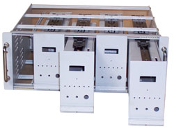
The IdeaA subrack with sub modulesPrevious experience had exposed me to the idea of using 19 inch subracks for mounting circuits inside submodules.

I originally envisaged the dev boards individually mounted inside these boxes. However preliminary investigation revealed that the enclosures were both expensive and used a lot of space which would greatly increase the rack space required to house these systems.

imx53 QSB eurocard carrier
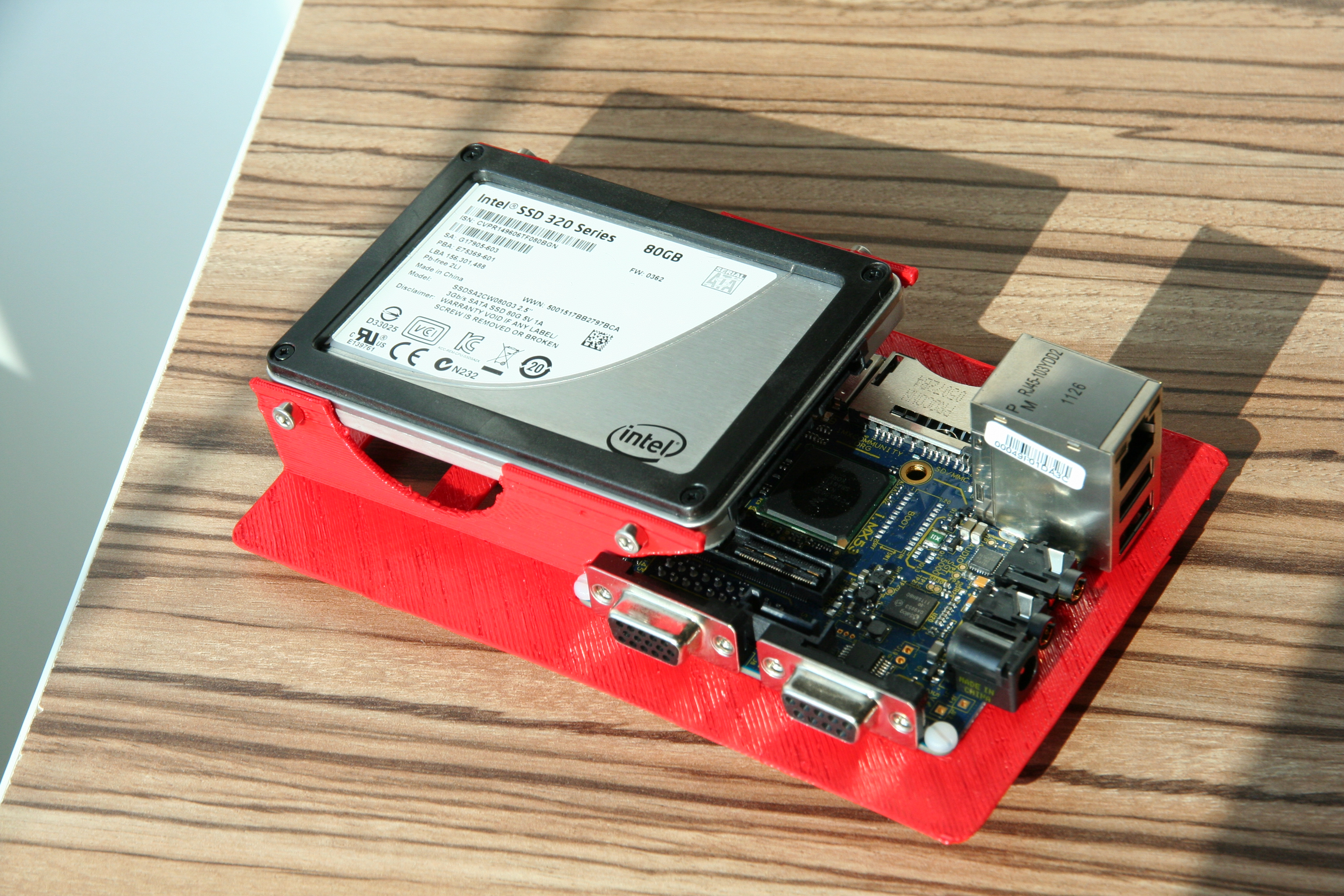
I decided to instead look at eurocard type subracks with carriers for the systems. Using my 3D printer I came up with a carrier design for the imx53 QSB and printed it. I used the basic eurocard size of 100mm x 160mm which would allow the cards to be used within a 3U subrack.

Once assembled it became apparent that each carrier would be able to share resources like power supply, ethernet port and serial console via USB just as the existing setup did and that these would need to be housed within the subrack.
The Prototype
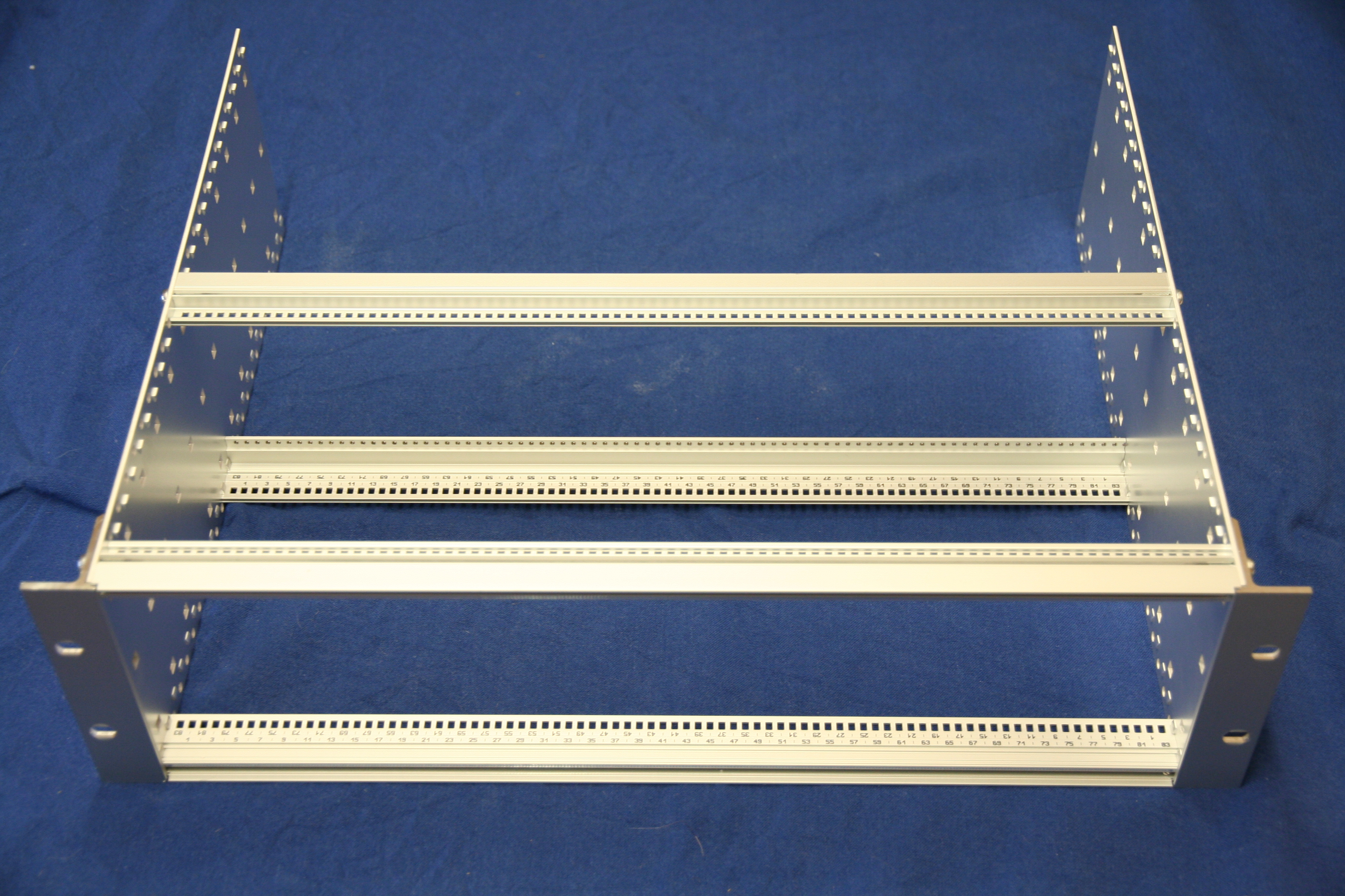
The carrier prototype was enough to get enough interest to allow me to move on to the next phase of the project. I purchased a Schroff 24563-194 subrack kit and three packs of guide rails from Farnell and assembled it.

Initially I had envisaged acquiring additional horizontal rails from Schroff which would enable constructing an area suitable for mounting the shared components behind the card area.

Rear profile for Schroff subrackUnfortunately Schroff have no suitable horizontal profiles in their catalog and are another of those companies who seem to not want to actually sell products to end users but rather deal with wholesalers who do not have their entire product range!

Printed rear profile for Schroff subrack
Undaunted by this I created my own horizontal rail profile and 3D printed some lengths. The profile is designed to allow a 3mm thick rear cover sheet attached with M2.5 mounting bolts and fit rack sides in the same way the other profiles do.

At this point I should introduce some information on how these subracks are dimensioned. A standard 19 inch rack (as defined in IEC 60297) has a width of 17.75 inches(450.85mm) between the vertical posts. The height is measured in U (1.75 inches)

A subrack must obviously fit in the horizontal gap while providing as much internal space as possible. A subrack is generally either 3 or 6 U high. The width within a subrack is defined in units called HP (Horizontal Pitch) which are 0.2 inches(5.08 mm) and subracks like the Schroff generally list 84 usable HP.

However we must be careful (or actually just learn from me stuffing this up ;-) as the usable HP is not the same thing as the actual length of the horizontal rails! The enclosures actually leave and additional 0.1 inch at either end giving a total internal width of 85HP (17 inches, 431.8 mm) which leaves 0.75 inches for the subrack sides and some clearance.

The Schroff subrack allows eurocards to be slotted into rails where the card centre line is on HP boundaries, hence we describe the width of a card in the slot in terms of HP

I cannot manufacture aluminium extrusions (I know it is a personal failing) nor produce more than 100 mm long length of the plastic profile on my printer.

Even if full lengths are purchased from a commercial service (120 euros for a pair including tax and shipping) the plastic does not have sufficient mechanical strength.

The solution I came up with was somewhat innovative, as an alternative a M5 bolt into a thread in the aluminium extrusion I used a 444mm long length of 4mm threaded rod with nuts at either end. This arrangement puts the extrusion under compression and gives it a great deal of additional mechanical strength as the steel threaded rod is very strong.

Additionally to avoid having to print enough extrusion for the entire length I used some 6mm aluminium tube as a spacer between 6HP(30.48mm) wide sections of the printed extrusion.

It was intended to use a standard modular PC power supply which is 150mm wide which is pretty close to 30HP (6 inches) so it was decided to have a 6HP section of rail at that point to allow a rear mounting plate for the PSU to be attached.

This gives 6HP of profile, 21HP(106.68mm) of tube spacer, 6HP of profile, 46HP(233.68 mm) of tube spacer and a final 6HP profile summing to our total of 85HP. Of course this would be unnecessary if a full continuous 85HP rail had been purchased, but 6 of 6 HP long profile is only 51 euro a saving of 70 euro.

To provide a flat area on which to mount the power switching, Ethernet switch and USB hubs I ordered a 170 x 431 mm sheet of 3mm thick aluminium from inspiredsteel who, while being an ebay company, were fast, cheap and the cutting was accurate.

Do be sure to mention you would prefer it if any error made the sheet smaller rather than larger or it might not fit, for me though they were accurate to the tenth of a mm! If you would prefer the rear section of the rack to be enclosed when you are finished, buy a second sheet for the top. For my prototype I only purchased a 170 x 280mm sheet as I was unsure if I wanted a surface under the PSU (you do, buy the longer sheet)

PC power supply mounted to back plateMounting the PSU was a simple case of constructing a 3 mm thick plate with the correct cutouts and mounting holes for an ATX supply. Although the images show the PSU mounted on the left hand side of the rack this was later reversed to improve cable management.

The subrack needed to provide Ethernet switch ports to all the systems. A TP-Link TL-SF1016DS 16-Port 10/100Mbps Switch was acquired and the switch board removed from its enclosure. The switch selected has an easily removed board and is powered by a single 3.3V input which is readily available from the ATX PSU.

Attention now returned to the eurocard carriers for the systems, the boards to be housed were iMX53 QSB and iMX6 SABRE Lite and a Raspberry Pi control system to act as USB serial console etc.

The carriers for both main boards needed to be 8HP wide, comprised of:
Although only 38 mm this is 7.5HP and fractions of an HP are not possible with the selected subrack.

With 8HP wide modules this would allow for ten slots, within the 84 usable HP, and an eleventh 4HP wide in which the Raspberry Pi system fits.

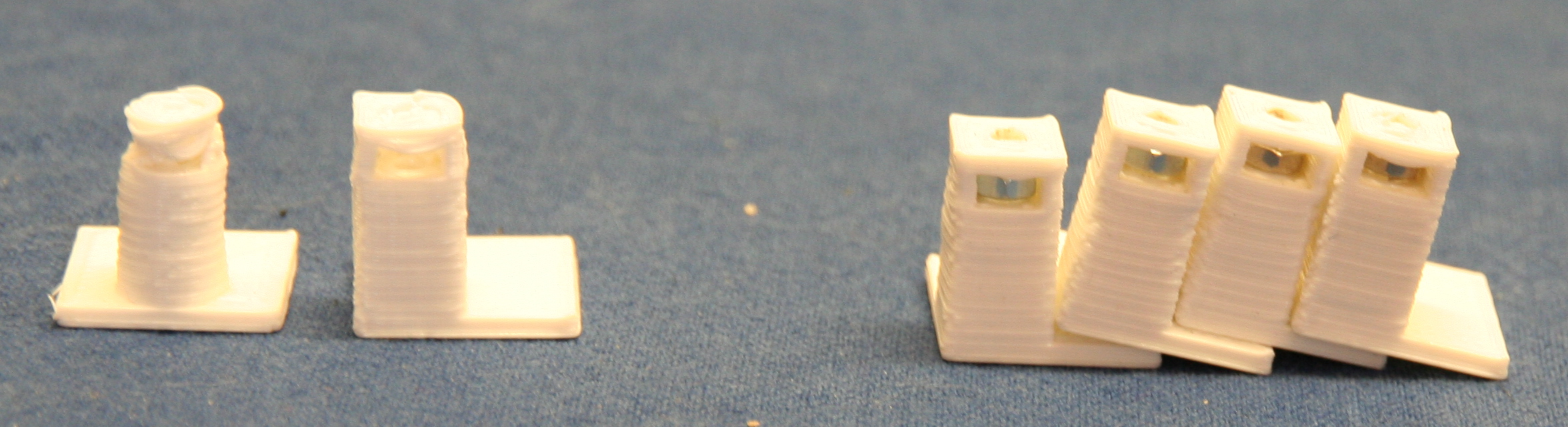
iMX6 SABRE Lite eurocard carrierCarrier designs for both the i.MX53 QSB and the i.MX6 SABRE Lite boards were created and fabricated at a professional 3D print shop which gave a high quality finish product and removed the perceived risk of relying on a personal 3D printer for a quantity of parts.

This resulted in changes in the design to remove as much material as possible as commercial 3D services charge by the cubic cm. This Design For Manufacture (DFM) step removed almost 50% from the price of the initial design.

i.MX53 QSB carriers with wiring loom
The i.MX6 design underwent a second iteration to allow for the heatsink to be mounted and not mechanically interfere with the hard drive (although the prototype carrier has been used successfully for a system that does not require a hard drive). The lesson learned here is to be aware that an design iteration or two is likely and that it is not without cost.

The initial installation was to have six i.MX53 and two i.MX6 this later changed to a five/four split, however the carrier solution allows for almost any combination, the only caveat (discovered later) is the imx53 carriers should be to the right hand side with the small 4HP gap at that end as they have a JTAG connector underneath the board which otherwise foul the hard drive of the next carrier.

Racked cards showing unwanted cable tails
A wiring loom was constructed for each board giving them a connector tail long enough to allow them to be removed. This was the wrong approach! if you implement this design (or when I do it again) the connector tails on the wiring loom should present all the connections to the rear at the same depth as the Ethernet connection.

The rack cables themselves should be long enough to allow the slides to be removed but importantly it is not desirable to have the trailing cable on the cards. I guess the original eurocard designers figured this out as they designed the cards around the standard fixed DIN connectors at the back of the card slots.

USB relay board with wiring loom attached
We will now briefly examine a misjudgement that caused the initially deployed solution to be reimplemented. As the design was going to use USB serial converters to access the serial console a USB connected relay board was selected to switch the power to each slot. I had previously used serial controlled relay boards with a USB serial convertor however these were no longer available.

Initial deployment with USB controlled relay board
All the available USB relay boards were HID controlled, this did not initially seem to be an issue and Linux software was written to provide a reasonable interface. However it soon became apparent that the firmware on the purchased board was very buggy and crashed the host computer's USB stack multiple times.

Deployed solutionOnce it became apparent that the USB controlled power board was not viable a new design was conceived. As the Ethernet switch had ports available Ethernet controlled relay boards were acquired.

Evolution of 3mm PCB pillars
It did prove necessary to design and print some PCB support posts with M3 nut traps to allow the relay boards to be easily mounted using double sided adhesive pads.

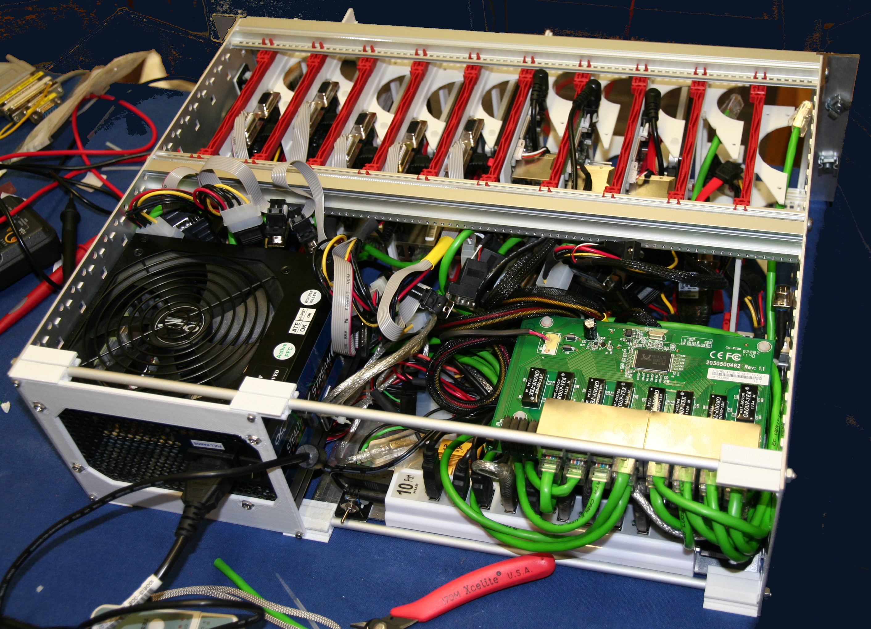
By stacking the relay boards face to face and the Ethernet switch on top separated using nylon spacers it was possible to reduce the cable clutter and provide adequate cable routing space.

A busbar for Ground (black) and unswitched 12V (yellow) was constructed from two lengths of 5A chock block.

An issue with power supply stability was noted so a load resistor was added to the 12V supply and an adhesive thermal pad used to attach it to the aluminium base plate.

Completed redesign
It was most fortunate that the ethernet switch mounting holes lined up very well with the relay board mounting holes allowing for a neat stack.

This second edition is the one currently in use, it has proved reliable in operation and has been successfully updated with additional carriers.

The outstanding issues are mainly centered around the Raspberry Pi control board:
  • Needs its carrier fitting. It is currently just stuck to the subrack end plate.
  • Needs its Ethernet cable replacing. The existing one has developed a fault post installation.
  • Needs the USB hub supply separating from the device cable. The current arrangement lets the hub power the Pi which means you cannot power cycle it.
  • Connect its switched supply separately to the USB hub/devices.
Shopping listThe final bill of materials (excluding labour and workshop costs) which might be useful to anyone hoping to build their own version.

Prices are in GBP currency converted where appropriate and include tax at 20% and delivery to Cambridge UK and were correct as of April 2013.

The purchasing was not optimised and for example around 20GBP could be saved just by ordering all the shapeways parts in one order.
Base subrack
ItemSupplierQuantityLine Price
Schroff 24563-194 subrack kitFarnell141.28
Schroff 24560-351 guide railsFarnell313.65
Schroff rack rear horizontal railShapeways2100.00
1000mm length of 4mm threaded rodB and Q11.48
170mm x 431mm x 3mm Aluminium sheetinspired steel240.00
PSU mounting plateShapeways135.42
PCB standoffShapeways422.30
160mm Deep Modular PC supplyCCL155.76
TP-Link TL-SF1016DS 16-Port 10/100Mbps-SwitchCCL123.77
8 Channel 16A Relay Board Controlled Via EthernetRapid2126.00
Raspberry PiFarnell126.48
USB Serial convertersCCL1037.40
10 port strip style USB HUBEbay17.00
Parts for custom Ethernet cablesRS1326.00
Parts for custom molex power cables (salvaged from scrap ATX PSU)Workshop1111.00
33R 10W wirewound resistor for dummy loadRS11.26
24pin ATX female connector pre-wiredMaplin12.99
Akasa double sided thermal padMaplin15.00
Small cable tie basesMaplin16.49
Miscellaneous cable, connectors, nylon standoffs, solder, heatshrink, zip ties, nuts, washers etc. Workshop120.00
Total for subrack603.28

The carriers are similarly not optimally priced as over five GBP each can be saved by combining shipping on orders alone. Also the SSD drive selection was made some time ago and a newer model may be more suitable.
i.MX53 QSB carrier
ItemSupplierQuantityLine Price
i.MX53 QSBFarnell1105.52
Intel 320 SSD 80GCCL1111.83
Carrier boardShapeways130.00
combined sata data and power (15 to 20cm version)EBay15.00
Low profile right angle 5.5mm x 2.1mm barrel jackEBay10.25
Parts for 9pin serial cable extensionRS15.00
Miscellaneous solder, heatshrink, nylon nuts, bolts and washersWorkshop15.00
Total for carrier262.60

i.MX6 SABRE Lite carrier
ItemSupplierQuantityLine Price
i.MX6 SABRE LiteFarnell1128.06
Intel 320 SSD 80GCCL1111.83
Carrier boardShapeways135.00
combined sata data and power (15 to 20cm version)EBay15.00
Low profile right angle 5.5mm x 2.1mm barrel jackEBay10.25
Parts for 9pin serial cable modificationRS12.00
Miscellaneous solder, heatshrink, nylon nuts, bolts and washersWorkshop15.00
Total for carrier287.14
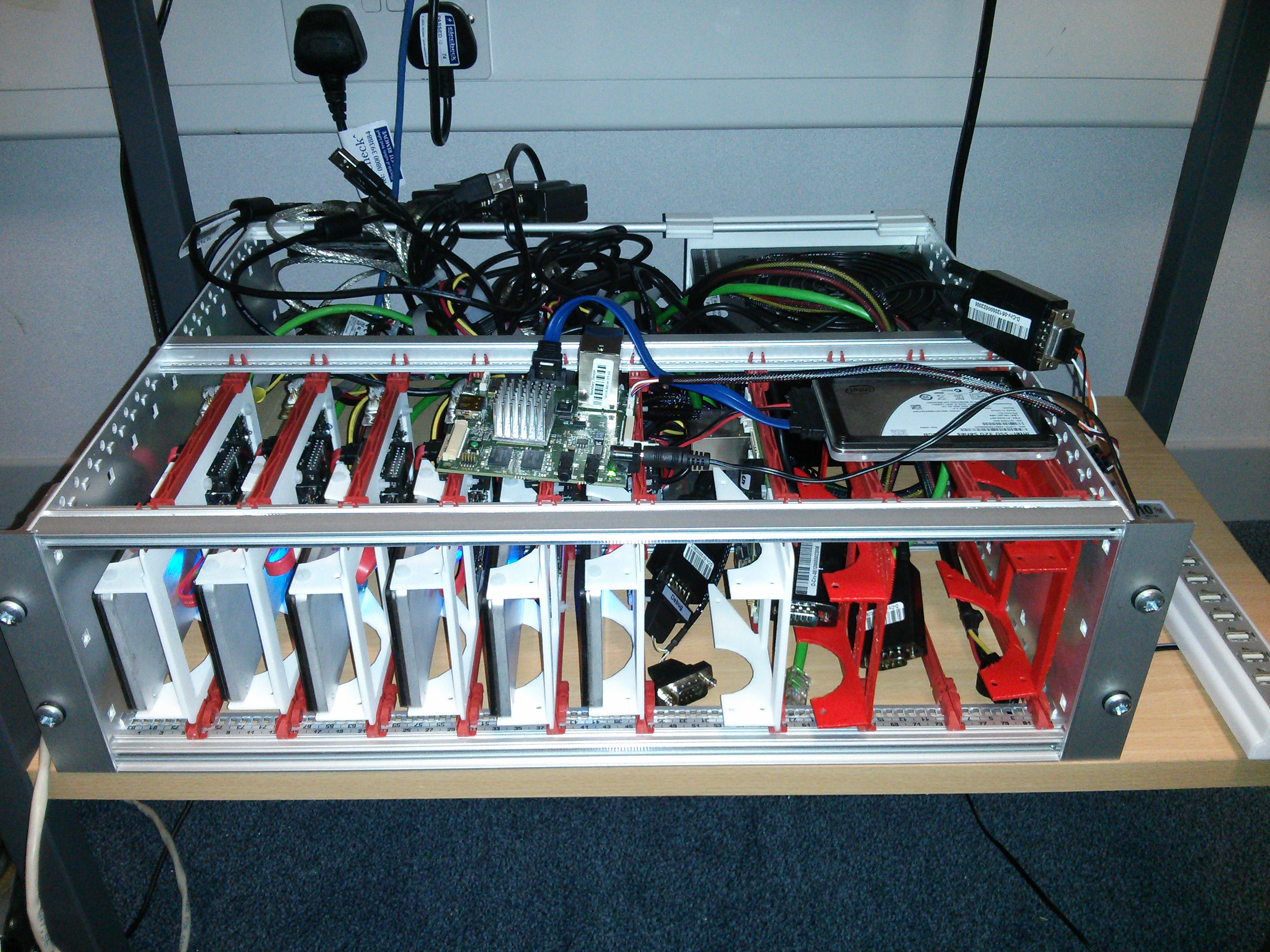
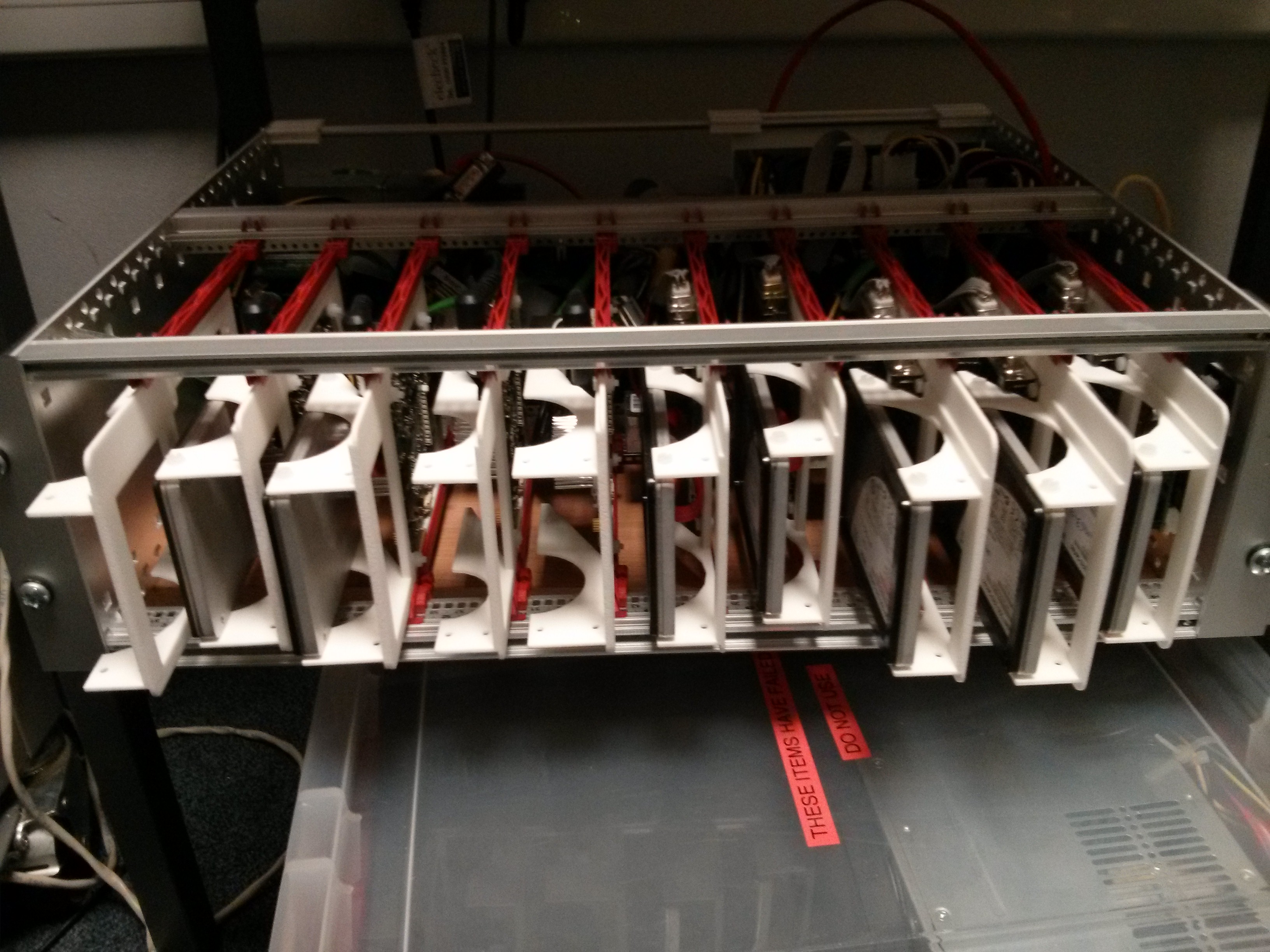
ConclusionThe solution works and in a 3U high 355mm deep subrack ten ARM development boards can be racked complete with local ethernet switching, power control and serial consoles.

Deployed system in situ configured as a build and test farm
The solution is neat and provides flexibility, density and reproducibility the "pile of stuff" solution failed to do.

For current prototype with nine filled slots the total cost was around 3000GBP or around 330GBP per slot which indicates a 100GBP per slot overhead over the "pile of stuff" solution. These figures omit the costs of the engineer and workshop time, which are estimated at an additional 1500GBP. Therefore a completed rack, fully filled with i.MX6 carriers costs around 5000GBP

Density could be increased if boards with lower height requirements were used however above twelve units there issues with Ethernet switch, power switch and USB port availability become a factor. For Example the 16 port Ethernet switch requires a port for uplink, one for each relay board and one for the console server which leaves only 12 ports for systems.

Addressing the outstanding issues would result in a much more user friendly solution. As the existing unit is in full time use and downtime is not easily scheduled for all ten systems, the issues are not likely to be fixed on the prototype and would have to be solved on a new build.

The solution is probably not suitable for turning into a product but that was not really the original aim. A commercial ARM blade server using this format would almost certainly use standard DIN connectors and a custom PCB design rather than adapting existing boards.

25 April 2013

Julien Danjou: OpenStack Design Summit Havana, from a Ceilometer point of view

Last week was the OpenStack Design Summit in Portland, OR where we, developers, discussed and designed the new OpenStack release (Havana) coming up. The summit has been wonderful. It was my first OpenStack design summit -- even more as a PTL -- and bumping into various people I've never met so far and worked with online only was a real pleasure! <figure> <figcaption>Me and Nick ready to talk about Ceilometer new features.</figcaption> </figure> Nick Barcet from eNovance, our dear previous Ceilometer PTL, and myself, talked about Ceilometer and presented the work that bas been done for Grizzly, with some previews of what we'll like to see done for its Havana release. You can take a look at the slides if you're curious. Design sessions Ceilometer had his design sessions during the last days of the summit. We noted a lot of things and commented during the sessions in our Etherpads instances. The first session was a description of Ceilometer core architecture for interested people, and was a wonderful success considering that the room was packed. Our Doug Hellmann did a wonderful job introducing people to Ceilometer and answering question. <figure> <figcaption>Doug explaining Ceilometer architecture.</figcaption> </figure> The next session was about getting feedbacks from our users. We had a lot of surprise to discover wonderful real use-cases and deployments, like the CERN using Ceilometer and generating 2 GB of data per day! The following sessions ran on Thursday and were much more about new features discussion. A lot ot already existing blueprints were discussed and quickly validated during the first morning session. Then, Sandy Walsh introduced the architecture they use inside StackTach, so we can start thinking about getting things from it into Ceilometer. API improvements were discussed without surprises and with a good consensus on what needs to be done. The four following sessions that occupied a lot of the days were related to alarming. All were lead by Eoghan Glynn, from RedHat, who did an amazing job presenting the possible architectures with theirs pros and cons. Actually, all we had to do was to nod to his designs and acknowledge the plan on how to build this. That last two sessions were about discussing advanced models for billing where we got some interesting feedback from Daniel Dyer from HP, and then were a quick follow-up of the StackTach presentation from the morning session. Havana roadmap The list of blueprints targetting Havana is available and should be finished by next week. If you want to propose blueprints, you're free to do so and inform us about it so we can validate it. The same applies if you wish to implement one of them! API extension I do think the API version 2 is going to be heavily extended during this release cycle. We need more feature, like the group-by functionnality. Healthnmon In parallel of the design sessions, discussions took place in the unconference room with the Healthnmon developers to figure out a plan in order to merge some of their efforts into Ceilometer. They should provide a component to help Ceilometer supports more hypervisors than it currently does. Alarming Alarming is definitely going to be the next big project for Ceilometer. Today, Eoghan and I started building blueprints on alarming, centralized in a general blueprint. We know this is going to happen for real and very soon, thanks to the engagements of eNovance and RedHat who are commiting resources to this amazing project!
22 April 2013

Daniel Pocock: Action week for Google Summer of Code students

This week (22 - 28 April) is the week that really matters most for those students who want to participate in Google Summer of Code. The deadline for student applications is next Friday (3 May), but if you don't spend time exploring project ideas this week, you won't be able to make a strong enough application. Here are the key things I need to see for potential students for the project areas I have offered to co-mentor in:
  1. Register on the Google site, Click here to register yourself (registration opens 22 April and closes 3 May).
  2. Create a page about yourself on the Debian wiki, you must copy the template used by the other students. Make sure you create a link from the student list to your own page. Think carefully about your project: what will be the final result of your work this summer? Describe what it will look like, how Debian people will use it, and explain these things on your wiki page, this will be critical to having Debian accept you.
Those are the essential things you must do before the deadline on 3 May. There are other things you should do as well:
  • Join the Summer of Code co-ordination mailing list
  • Join the mailing lists for whichever open source project and/or Debian packaging team is relevant to your proposed GSoC project
  • On the mailing list, send an email introducing yourself, giving us the link to your wiki page.
To maximize the chance that the Debian project will accept you, it is very important that you interact with us and show us that you understand software development. I am going to try and make this easier: for each of my projects, I've put some wishlist items in the Debian bug tracker. These are all easy tasks that a student can potentially complete. Just do the following:
  • Pick a task from the bug tracker
  • Send an email to the bug tracker (e.g. <bug-number>@bugs.debian.org>) explaining that you will work on the task (and make sure nobody else is already working on it, just look to see if any other emails are attached to the bug report)
  • Write the patch, test it and email the patch to the bug report
Here are the links to the bug lists for each of the packages. You can also pick any other wishlist bug in any related package, but if you are not sure, just pick one of these: If you already have a history of contributing to free software, it is essential that you tell us about it. This will increase the chances that your application is successful. Specifically, on your Debian wiki page, you should include links to any of the following:
  • Emails you sent to open source communities contributing patches or analysis of bugs (give a link to your message in the email archive for the list)
  • Your github account profile page, if you have one
  • Your Sourceforge account profile page, if you have one
  • Any other similar links
Debian receives many applications every year. To help you succeed, you need to think about how Debian will benefit from your work. Use Google to search the Debian site for previous discussions about your idea. Find out the names of Debian Developers who are interested in the same subjects, and email us or email the public mailing lists of the Debian project, for example, debian-devel. Make sure your email includes links to previous discussions or wiki pages about the idea, explain how you can help and ask the community for suggestions and guidance to refine your project proposal. Debian is an open community and we are all very keen to discuss your ideas and help you get involved. DebConf For all students, attending free software events is a great opportunity to meet the community. Of particular relevance for those in Europe, attending DebConf13 in Switzerland is a great way to meet GSoC mentors and other developers. Switzerland's central location is extremely convenient for anybody in Western Europe and it is also Debian's 20th birthday, so it is anticipated DebConf could be more special than usual this year. Please put it in your calendar and subscribe to the debconf-discuss mailing list so you will know when registration opens and other practical details are announced.

17 April 2013

Daniel Pocock: Switzerland Schilthorn with 007 (leg 3)

Friday's video of the 2nd leg of the cable car journey was quite popular, Ganglia stats for the video server can't be wrong: The first leg was skipped because of the low cloud cover. Weather reports in Switzerland, such as www.meteosuisse.ch often show a distinction between the low clouds and high clouds, because many Swiss mountain resorts are high enough to enjoy ample sunshine by virtue of their altitude even when cities like Zurich and Geneva are overcast. Now for the third leg, rising up to Berg. In the video, it is hard to gauge the size of the rocky cliffs along the route, but looking at the cable car's shadow will give a clue. As the cable car approaches the station in Berg, it feels like it takes forever to complete the journey. That is because the rocks are so much bigger than they appear from a distance. <video controls="" height="340" poster="http://upload.wikimedia.org/wikipedia/commons/thumb/0/03/Schilthorn_with_Bernese_Alps%2C_2012_August.jpg/800px-Schilthorn_with_Bernese_Alps%2C_2012_August.jpg" width="560">
<source src="http://video.danielpocock.com/VID_20121025_122453.m4v" type="video/mp4"></source>
<source src="http://video.danielpocock.com/VID_20121025_122453.webm" type="video/webm"></source>
</video> The final leg to the Schilthorn summit will appear shortly. I understand many people are starting to contemplate their DebConf13 travel and summer holidays - please feel free to email me if you'd like me to post a video of some other feature in Switzerland.
AttachmentSize
ganglia-schilthorn2.png8.71 KB

Joerg Jaspert: tmux - tm update

Just did a small update to my tm helper script. There is now a new variable, TMSESSHOST. If that is set to false, the hostname of the current machine won t be prepended to the generated session name. true is the default, as that was the behaviour in the past. It now can attach to any session, not just the ones it created itself, thus nearly entirely removing my need of ever calling tmux directly. And cosmetically - window names for sessions defined in the .tmux.d directory are no longer plain Multisession , but the session name as defined in the file. If you are interested, you can get it over here from my git repository of misc stuff

12 April 2013

Craig Small: Pie Charts in TurboGears

You might of looked at Ralph Bean s tutorial on graphs and thought, that s nice but I d like something different. The great thing about ToscaWidgets using the jqPlot library is that pretty much anything you can do in jqPlot, you can do in ToscaWidgets and by extension in TurboGears. You want different graph types? jqPlot has heaps! My little application needed a Pie Chart to display the overall status of attributes. There are 6 states an attribute can be in: Up, Alert, Down, Testing, Admin Down and Unknown. The Pie Chart would show them all with some sort of colour representing the status. For this example I ve used hard-coded data but you would normally extract it from the database using a TurboGears model and possibly some bucket sorting code. I ve divided my code into widget specific, which is found in myapp/widgets/attribute.py and the controller code found unsurprisingly at myapp/controllers/attribute.py Also note that some versions of ToscaWidgets have a bug which means any jqPlot widget won t work, version 2.0.4 has the fix for issue 80 that explains briefly the bug. The widget code looks like this:
from tw2.jqplugins.jqplot import JQPlotWidget
from tw2.jqplugins.jqplot.base import pieRenderer_js
import tw2.core as twc
 
class AttributeStatusPie(JQPlotWidget):
  """
  Pie Chart of the Attributes' Status """
  id = 'attribute-status-pie'
  resources = JQPlotWidget.resources + [
  pieRenderer_js,
  ]
 
  options =  
  'seriesColors': [ "#468847", "#F89406", "#B94A48", "#999999", "#3887AD", "#222222"], 
  'seriesDefaults' :  
  'renderer': twc.js_symbol('$.jqplot.PieRenderer'),
   ,
  'legend':  
  'show': True, 
  'location': 'e',
   ,
   
Some important things to note are: Next the controller needs to be defined:
from myapp.widgets.attribute import AttributeStatusPie
 
@expose('myapp.templates.widget')
  def statuspie(self):
  data = [[
  ['Up', 20], ['Alert', 7], ['Down', 12], ['Admin Down', 3], ['Testing', 1], ['Unknown', 4],
  ]]
  pie = AttributeStatusPie(data=data)
  return dict(w=pie)
And that is about it, we now have a controller path attributes/statuspie which shows us the pie chart.
My template is basically a bare template with a $ w.display n in it to just show the widget for testing.
Pie Chart in Turbogears

Pie Chart in Turbogears

11 April 2013

Bdale Garbee: Batteries and Pyro Circuits

Keith and I have discovered a change in the behavior of the protection circuits integrated in the LiPo batteries we sell for use with Altus Metrum products that poses a risk for our customers. This post is meant to document what we now know, communicate changes we're planning as a result, and explain what we think flyers of our existing electronics and batteries may want to do to maximize their chances of successful flights. Background Choosing batteries and designing pyro circuits for high power rocketry avionics involves a variety of trade-offs. Reliability is the highest concern, both because nobody wants to lose an airframe due to a failed pyro event, and also because airframes recovering anomalously have safety implications. But we also care about other factors including cost and weight, and usually want to minimize the complexity of both the electronics and the overall installation. The objective of a pyro circuit is to dump enough energy rapidly into an electric match to cause it to catch fire. We need batteries both to power the electronics that decide when to fire the charge, and to provide the energy that actually ignites the match. The two most common battery types seen in the rocketry hobby are alkaline cells, often the nominal 9V rectangular variety, and rechargeable batteries based on Lithium Polymer (LiPo) chemistry. LiPo cells are 3.7 volts per cell nominal voltage, are very light, and have a high energy density. LiPo capacity is measured in units of current times time, so an 850mAh cell should be able to deliver 850 milliamps for an hour. The battery industry also uses something called a "C rate" to describe how fast the battery can be usefully discharged, wich is a multiplier relative to the battery capacity. So a battery with 850mAh capacity and a "2C" rating can deliver current at a sustained rate of 1700mA until discharged, while the same capacity at a "5C" rating can deliver 4250mA. By comparison, most 9V alkaline batteries are actually composed of 6 individual 1.5V cells enclosed in a wrapper. It's hard to get hard numbers for capacity and discharge rate, since in an alkaline cell the two are not independent, and the discharge rate is related to the volume of each individual cell. The data sheet for an Energizer 522 shows just over 600mAh at a 25mA discharge rate, dropping to about 300mAh at a 500mA discharge rate. Importantly for use in pyro circuits, LiPo cells have a very low source impedance, which means they can source immense amounts of current. It's not unusual for cells in the 1000mAh range to have ratings in excess of 30C! Because this rapid discharge ability can pose a risk of fire, it's common for LiPo cells to come with a "protection board" integrated into the battery assembly that is designed to limit the current to some rate such as 2C continuous duty. In large airframes, or projects that involve staging, air-starts, or other complex pyro event sequences, the most reliable approach will always be to use separate batteries for the control electronics and the source of pyro firing power. In the limit, having separate pyro batteries for each pyro charge with the control electronics only providing the switching to connect the batteries to the charges could even make sense. But for most airframes, this is overkill, and the increases in mass, volume, and wiring complexity just don't make sense. The challenge, then, is how to design electronics that will robustly initiate pyro events without negatively affecting the rest of the electronics when operating from a single shared battery. Altus Metrum Pyro Circuits The very first prototypes of TeleMetrum were designed to use a single-cell LiPo battery, and had an on-board 100mA charging circuit. Because we needed 5 volts to power the accelerometer, we had a small switching regulator that up-converted the LiPo voltage, and we used some of that regulator's output to charge a 1000uF capacitor. The pyro circuit used Fairchild FDN335N N-channel MOSFET switches in a low-side switching configuration to dump the energy stored in the capacitor through an attached ematch. Those FETs had an on resistance of under a tenth of an ohm in our operating conditions. The circuit worked very reliably, but the 1000uF electrolytic cap was huge and we struggled with the mechanics of such a large part hanging off the board... It turns out that 3.7 volts is way more than enough to fire a typical low-current e-match or equivalents like the Quest Q2G2 igniters. In fact, bench testing with a good digital oscilloscope showed that a typical e-match with resistance of 1.3-1.8 ohms will fire in approximately 13 microseconds when hit with the nominal 3.7 volts from a LiPo. So, starting with our v0.2 boards, we switched to using the LiPo battery voltage directly to fire the pyro charges, eliminating the clunky electrolytic capacitor entirely. We also switched to the Fairchild FDS9926A dual N-channel MOSFET whose specs are better in all regards for our application. The on resistance is down around 40 milli-ohms in our circuit, such that the current ratings are much higher (FET current limits are primarily driven by how much heat is generated due to current flowing through the channel's on resistance). Because using the LiPo voltage directly means we're effectively temporarily putting a very low resistance across the battery during the pyro events, the input voltage to the voltage regulator gets pulled down. To ensure the processor could "ride through" these events, we added a 100uF surface mount bulk capacitor on the 3.3 volt regulated voltage rail, which bench testing demonstrated was more than sufficient to maintain processor operation through pyro events. And that is essentially the same pyro circuit on all the boards, both TeleMetrum and TeleMini, that we have shipped to date. What's Changed The LiPo batteries we source and sell with our electronics come with a protection board and cable terminated in a 2-pin, 2mm "JST" connector. The specs on the protection board have always been "2C continuous", but we observed the ability to source much higher currents for short periods such as the 13 micro-seconds or so required to fire an e-match. Thus these protection circuits seemed just fine .. we could fire e-matches with a burst of current but were protected against short circuits in the wiring or our boards by the 2C continuous limit. Unfortunately, the most recent batch of batteries we sourced seem to have a much "twitchier" protection circuit. We can draw more than 2C for short bursts, but not as much as with prior boards, and not for as long an interval. With a 1 ohm power resistor on the pyro terminals of one of our boards, we get about 9 milliseconds of power before the protection circuit cuts in and shuts the battery down. The power stays down until all load is removed, which at least means the board is turned off and back on again, and in some cases could even mean the battery is unplugged and re-plugged since we draw trace current to keep the GPS memory alive even when the power is turned off, and at least some of the new batteries see that as enough to keep the power turned off after an over-current event. For many e-matches, this isn't an issue, since 9 milliseconds is way longer than the 13 microseconds needed to fire the charge. Unfortunately, we've discovered that many of the e-matches bought and used in the rocketry hobby are actually made for use in the fireworks industry, where it is desireable to retain continuity after firing so that series connections of e-matches all can fire even if some fire faster than others! This means that while the resistance goes up some after firing, sometimes the drain on the battery remains sufficient to cause the protection circuit to kick in even after the pyro charge has fired. What We're Doing About It If we remove the protection circuit from the LiPo (or jumper around it), all existing Altus Metrum products will operate successfully with pyro charges thave have an effective resistance of as low as 1 ohm. That's lower than any e-match or Q2G2 we've ever seen, so in effect what this means is that if you have an existing Altus Metrum flight computer, and you remove the LiPo protection circuit, you're good to go. This does not really make things any more "dangerous", since our battery chargers are all current limited and our discharge patterns will never cause heating of the battery. Frankly, in a rocket, the most likely way to cause a problem with a LiPo is by smashing or puncturing the actual battery during bench work or during a crash... and those cause the same problems with or without a protection board present. In the future, we will ship batteries that have either a much higher C rating on the protection circuit, or have no protection circuit at all. The number of problems reported by actual customers that we think should be attributed to LiPo protection circuit boards is very low, and we suspect most of our customers who are happily flying their boards can continue to do so. Ground testing where you fire pyro charges (or at least e-matches) using RF to issue the commands (not USB, since the LiPo charger is running any time USB is connected!) will confirm whether there's a problem. If the board resets (does startup beeps) after a pyro event, or shuts down completely (no LED activity), then you have a problem. If the matches light and the board keeps running, you're good to go. However, any Altus Metrum customer with LiPo batteries sourced from us or our distributors who is worried about this problem (even if you haven't seen problems in ground testing or previous flights), and who doesn't want to try soldering on the battery circuit board yourself, is welcome to contact us about removing the protection circuit for you. We won't charge anything other than shipping. To take advantage of this offer, just send email to fixmybattery@altusmetrum.org telling us how many of which capacity batteries you have that you'd like updated, and we'll respond with an RMA number and shipping details. Going Even Further As previously indicated, with the LiPo protection circuits removed, all of our current products will work reliably with at least 1 ohm across the pyro terminals. That should cover all real-world flying conditions just fine, but we're not satisfied yet. We've designed a new pyro control circuit that transfers the maximum possible energy to the load regardless of battery voltage without ever allowing the voltage to the processor to droop at all. We're testing this new circuit in various prototypes now, and if it pans out it will probably show up first in MegaMetrum and then trickle down to TeleMetrum and TeleMini as those products are updated later this year. The new pyro circuit tolerates 0 ohms (dead shorts) on the pyro terminals for as long as the battery can provide current, which is as good as it gets. We think the circuit is clever enough that we'll probably write more about it once we're finished validating it.
3 April 2013

Daniel Pocock: The multiple repository conundrum in Linux packaging

I'm involved with a number of free software projects as both a developer and as the maintainer of packages for various distributions such as Debian (which also feeds packages to Ubuntu) and OpenCSW. I regularly come across the following situations:
  • Developers of great software who would like to see it packaged, distributed and promoted conveniently through platforms like Debian
  • Users of Linux distributions who are keen to use free software if it is presented in a convenient and accessible manner they are familiar with.
Sadly, despite everybody having the best intentions, there is sometimes a chasm separating these two groups of people. Upstream developers are often busy developing new features and don't have time to work on the intricacies of packaging. I hope that by sharing a few of my own experiences I can help more developers get their software packaged more easily. Fortunately, a number of great tools like git-buildpackage have emerged for streamlining the packaging process, but this has also created more confusion for developers who have their own git repositories and don't quite understand how the Debian git repository and patching process relates to their own repository. The autotools world Here, I focus on autotools based software, because this type of software has it's own peculiar issues when packaging. In particular, these issues appear when using a version control system to track upstream releases. Some of the concepts can be applied to the study of regular Makefile or cmake projects as well. Here is a diagram giving an overview: Let's work through each of the steps in the diagram: The upstream release
  1. The developer/release manager updates the version number in
    configure.ac
    (sometimes called configure.in) and tags the code. (Usually this tag is on a dedicated release branch.)
  2. The developer checks out a copy of the code from the tag into a fresh working directory
  3. The developer runs the autoreconf/automake tools, usually from a bootstrap script. These tools create a number of new files that don't exist in the project repository. Finally, the developer runs
    make dist
    , which puts all the files,
    including the generated files, into a distribution tarball. It is worth emphasizing this point: the tarball is not just an archive of the files from the repository/tag, it also contains a number of
    files generated by autotools.
  4. The developer uploads the tarball to a web site such as the Sourceforge download page. Usually a release announcement is made now containing checksums for the tarball.
At this point, the upstream developer's work is done and packaging teams from various projects such as Debian will take over. Sometimes, the upstream developer is also building the packages and continues
onto the next steps himself: Packaging
  1. The package is downloaded by the package maintainer
  2. If it is the first download, the maintainer creates a new git repository. If it has been packaged before, he clones the repository. The important point here is that this is not the upstream repository, it is an independent repository for Debian packaging. The maintainer uses the git-import-orig tool to import the upstream tarball into the packaging repository. The git-import-orig tool captures an exact snapshot of the upstream release tarball contents in a branch called upstream. One point where the Debian repository differs fundamentally from the upstream repository is that all files from the tarball will be tracked in the Debian git repository, even those automatically generated files that were created by autotools and don't exist in the upstream repository.
  3. The maintainer creates or updates the various artifacts for packaging. These files are kept on the master branch, and the tarball contents from the upstream branch are merged into master to create packages.
  4. When the maintainer feels the code is ready, he will check out a clean copy of the repository to build the package from.
  5. The maintainer executes a tool such as git-buildpackage or regular dpkg-buildpackage, which creates the *.deb files.
  6. The files are checked with a tool like lintian and some manual testing/installation. If all is OK, a tag is made in the packaging repository, with a suffix appended to the upstream version number to indicate which iteration of the package it applies to.
AttachmentSize
release-packaging-workflow.dia3.97 KB

26 March 2013

Ryan Kavanagh: Setting up full-disk encryption in OpenBSD 5.3

I recently decided to try out a snapshot of OpenBSD 5.3, intrigued by the notice that
softraid(4) RAID1 and crypto volumes are now bootable on i386 and amd64 (full disk encryption).
I ve always used an encrypted LVM (as setup by the alternate CD) with a fully encrypted root on my netbook and laptop when running Debian/Kubuntu and never noticed much a performance hit. Unfortunately, I m not the only one who has noticed a significant drop in performance with full-disk encryption on OpenBSD. Although the steps required to setup full-disk encryption (as opposed to requiring manual intervention at boot or the equivalent of loop-mounted encrypted images via vnconfig(8)) on OpenBSD are not explicitly documented anywhere, searching through the mailing lists, man pages, and trial and error provided the following steps:
  1. Boot from your install media. Select the (S)hell option.
  2. Assuming the disk you re installing to is wd0 , run fdisk -i wd0 if you re on an i386. If I m not mistaken, you can skip to the following step otherwise.
  3. Run disklabel -E wd0. Create a label (typically b) of the appropriate size of type swap for swap, and then add a label a using the remainder of the space of type RAID. We aren t going to put swap on our crypto device since OpenBSD has encrypted the swap partition by default since 2005.
  4. Setup the crypto volume as described in bioctl(8). You will be prompted for a passphrase and presented with a message along the lines of softraid0: SR CRYPTO volume attached as sd0 on successful setup. I used bioctl -c C -l /dev/wd0a softraid0 where - -c C specifies a device with raidlevel CRYPTO , - -l /dev/wd0a specifies the label of type RAID created in step 3 to use for the CRYPTO device, and - softraid0 is the softraid device to configure (this value should work unless you already have a softraid0 device).
  5. exit from the shell and (I)nstall as normal, installing to the disk sd0 (or whichever disk the crypto volume got attached as). In the partitioning dialog, you may need to manually adjust things since the auto-partitioning creates an additional swap label on sd0, which we don t need given we already have wd0b.
  6. Using ed(1), add the line 1a8bab44e9cc178d.b none swap sw to /mnt/etc/fstab, assuming that 1a8bab44e9cc178d is the DUID associated with wd0 (you can find this out by running sysctl hw.disknames, which will output something like hw.disknames=wd0:1a8bab44e9cc178d,cd0:,rd0:6ce80c78714fa32f,sd0:fce7bfa23c8ec20d; just search for the DUID associated with wd0). Alternatively, wait until you boot into your system, and add it to your /etc/fstab using vi(1) or mg(1).
  7. Reboot, and you ll be prompted for your passhprase. You re done!
Here s a screenshot of steps 1 through 4. Steps 1 through 4 Here s a screenshot of the passphrase prompt, after successfully entering the passphrase: Passphrase prompt If I ve made any errors in the steps above, please point them out in the comments below or by sending me an email.

21 March 2013

Martin Pitt: python-dbusmock 0.6 released

I just pushed out a new python-dbusmock release 0.6. Calling a method on the mock now emits a MethodCalled signal on the org.freedesktop.DBus.Mock interface. In some cases this is easier to track than parsing the mock s log or using GetMethodCalls. Thanks to Lars Uebernickel for this. DBusMockObject.AddTemplate() and DBusTestCase.spawn_server_template() can now load local templates from your own project by specifying a path to a *.py file as template name. Thanks to Lucas De Marchi for this feature. I also wrote a quite comprehensive template for systemd s logind. It stubs out the power management functionality as well as user/seat/session objects, and is convincing enough for loginctl. Some bits like AttachDevice is missing, as this sounds unlikely to be required for D-BUS mock tests, but please let me know if you need anything else. The mock processes now terminate automatically if their connected D-BUS goes down, as advertised in the documentation. You can get the new tarball from Launchpad, and I uploaded it to Debian experimental now. Enjoy!

6 March 2013

Keith Packard: composite-swap

Composite and Swap Getting it Right Where the author tries to make sure DRI3000 is going to do what we want now and in the future DRI3000 The basic DRI3000 plan seems pretty straightforward:
  1. Have applications allocate buffers full of new window contents, attach pixmap IDs to those buffers and pass them to the X server to get them onto the screen.
  2. Provide a mechanism to let applications know when those pixmaps are idle so that they can reuse them instead of creating new ones for every frame.
  3. Finally, allow the actual presentation of the contents to be scheduled for a suitable time in the future, generally synchronized with the monitor. Let the client know when this has happened in case they want to synchronize themselves to vblank.
The DRI3 extension provides a way to associate pixmap IDs and buffers, and given the MIT-SHM prototype I ve already implemented, I think we can safely mark this part as demonstrably implementable. That leaves us with a smaller problem, that of taking pixmap contents and presenting them on the screen at a suitable time and telling applications about the progress of that activity. In the absence of compositing, I m pretty sure the initial Swap extension design would do this job just fine, and should resolve some of the known DRI2 limitations related to buffer management. And, I think that goal is sufficient motivation to go and implement that. However, I wanted to write up some further ideas to see if the DRI3000 plan can be made to do precisely what we want in a composited world. The Composited Goal To make sure we re all on the same page, here s what I expect from the Swap extension in a composited world:
  1. Application calls Swap with new window pixmap
  2. Compositor hears about the new pixmap and uses that to construct a new screen pixmap
  3. Compositor calls Swap with new screen pixmap
  4. Vertical retrace happens, executing the pending swap operation
  5. Compositor hears about the swap completion for the screen
  6. Application hears about the swap completion for its window
In particular, applications should not hear that their swap operations are complete until the contents appear on the screen. This allows for applications to throttle themselves to the screen rate, either doing double or triple buffering as they choose. I didn t add steps here indicating buffers going idle or being allocated, because I think that should all happen behind the scenes from the application s perspective. Many applications won t care about the swap completion notification either, but some will and so that needs to be visible. Redirected Swaps? Owen Taylor suggested that one way of getting the compositor involved would be to have it somehow redirect Swap operations, much like we do with window management operations today. I think that idea may be a good direction to try:
  1. Application calls Swap with new window pixmap
  2. Swap is redirected to compositor, passing along the new window pixmap
  3. Compositor constructs a new screen pixmap using the new window pixmap
  4. Compositor calls Swap on the screen and the window, passing the new screen pixmap and the new window pixmap. When the screen update occurs, the screen and the window both receive swap completion events.
This has the added benefit that the X server knows when the compositor is expecting window pixmaps to change like this the compositor has to explicitly request Swap redirection. Window Pixmap Names and GEM Buffer Handles One issue that swapping window pixmaps around like this brings up is how to manage existing names for the window pixmap. Right now, applications expect that window pixmaps will only change when the window is resized. If the Swap extension is going to actually replace the window pixmap when running with a suitable compositor, then we need to figure out what the old names will reference. Are there non-compositor applications using NameWindowPixmap that matter to us? How about non-compositor applications using TextureFromPixmap to get a GEM handle for a window pixmap? For now, I m very tempted to just break stuff and see who complains, but knowing what we re breaking might be nice beforehand. Idling Pixmaps When an application is done drawing to a window pixmap and has passed it off to the X server for presentation, we d like for that pixmap to be automatically marked as discardable as soon as possible. This way, when memory is tight, the kernel can come steal those pages for something critical. Of course, applications may not want to let the server mark the pixmap as idle after being used, so a flag to the Swap call would be needed. Ideally, the pixmap would become idle immediately after the pixmap contents have been extracted. In the absence of a compositor, that would probably be when the Swap operation completes. With a compositor running, we d need explicit instruction from the compositor telling us that the window pixmap was now idle :
 
    SwapIdle
    drawable: Drawable
    pixmap: Pixmap
       
 
Furthermore, the application needs to know that the pixmap is in fact idle. I think that we ll need a synchronous X request that marks a buffer as no longer idle and have that return whether the buffer was discarded while idle. It doesn t seem sufficient to use events here as the application will need to completely reconstruct the pixmap contents in this case. This reply could also contain information about precisely what contents the pixmap does contain.
 
    SwapReuse
    drawable: Drawable
    pixmap: Pixmap
       
    valid: BOOL
    swap-hi: CARD32
    swap-lo: CARD32
 
Pixmap Lifetimes and Triple Buffered Applications If we redirect the Swap operation and send the original application window pixmap ID to the compositor, what happens when the application frees that pixmap before the compositor gets around to using the contents? Surely the Compositor must handle such cases, and not just crash. However, I m fine with requiring that the application not free the pixmap until told by the compositor.

3 March 2013

Petter Reinholdtsen: Frikanalen - Complete TV station organised using the web

Do you want to set up your own TV station, schedule videos and broadcast them on the air? Using free software? With video on demand support using free and open standards? Included a web based video stream as well? And administrate it all in your web browser from anywhere in the world? A few years now the Norwegian public access TV-channel Frikanalen have been building a system to do just this. The source code for the solution is licensed using the GNU LGPL, and available from github. The idea is simple. You upload a video file over the web, and attach meta information to the file. You select a time slot in the program schedule, and when the time come it is played on the air and in the web stream. It is also made available in a video on demand solution for anyone to see it also outside its scheduled time. All you need to run a TV station - using your web browser. There are several parts to this web based solution. I'll mention the three most important ones. The first part is the database of videos and the schedule. This is written in Django and include a REST API. The current database is SQLite, but the plan is to migrate it to PostgreSQL. At the moment this system can be tested on beta.frikanalen.tv. The second part is the video playout, taking the schedule information from the database and providing a video stream to broadcast. This is done using CasparCG from SVT and Media Lovin' Toolkit. Video signal distribution is handled using Open Broadcast Encoder. The third part is the converter, handling the transformation of uploaded video files to a format useful for broadcasting, streaming and video on demand. It is still very much work in progress, so it is not yet decided what it will end up using. Note that the source of the latter two parts are not yet pushed to github. The lead author want to clean them up a bit more first. The development is coordinated on the #frikanalen IRC channel (irc.freenode.net), and discussed on the frikanalen mailing list. The lead developer is Benjamin Bruheim (phed on IRC). Anyone is welcome to participate in the development.

Next.

Previous.