
We've had sporadic
Altus Metrum customer reports
about RF susceptibility issues with their
TeleMetrum installations. In almost
every case, these problems have been completely resolved by either making
sure the system battery has sufficient charge before launch, or through the
application of standard engineering techniques such as twisting wire pairs
to reduce differential coupling. However, even when every technique we could
think of had been applied, once in a while someone still had issues.
Around the time of LDRS this year, the incidence of such reports seemed to
increase. One customer, in particular, had an installation in which he
virtually always saw continuous resets of the board once his 54mm airframe
was put on a launch rail, and several customers reported seeing board resets
during ejection charge firing.
Keith and I saw a board
reset during main charge firing happen in person at
NCR's Oktoberfest, and with a couple days available
to work together after that launch, we decided it was time to figure out
what was really going on.
Here's what we've learned.
In bench testing, it quickly became clear that the problem was the 3.3
volt power supply rail getting pulled down far enough to reset the CPU.
This most frequently happened during ejection
charge firing, when the input of the LDO regulator is pulled down by the
near-short presented by the e-match when a pyro FET is turned on. To keep
the 3.3 volt rail voltage up during firing, we include a 100uF bulk capacitor
on the regulator's output. In all of our prior bench testing, we never saw
the 3.3 volt rail droop significantly. Clearly something had changed... or
maybe several things had changed?
The first thing I wondered about was whether the new Kalman filtering code,
which requires more compute cycles from the processor, might be consuming
enough more power to pull the rail down faster during charge firing. After
poking around at it, though, we have no data to suggest the new code makes a
measurable difference in power consumption.
The next thing we pondered was that at least some of the e-matches we and
others are using in the hobby now come from the fireworks industry, where it
is apparently considered a feature for the match to retain continuity after
firing. This means the input of the LDO gets held down for longer than with
the e-matches we used to use and Quest Q2G2 igniters that open when fired.
But that still didn't make sense as the root cause, as we chose the FET
firing time such that even with a dead short across the igniter terminals,
the 3.3 volt rail wouldn't be pulled down far enough to cause trouble during
firing.
One of the big changes between v1.0 and v1.1 on TeleMetrum was that the newer
boards incorporate a better reset circuit. This helps ensure the GPS chip
always comes up running at power on, which was a problem at temperature
extremes with older boards. However, a side-effect of this change is that
a v1.1 board will reset any time the 3.3 volt rail drops below 3.15 volts,
whereas older boards didn't trip until a much lower voltage. So the recent
increase in reports might just be related to more v1.1 boards being placed
in service?
While experimenting on the bench, we observed that injecting RF energy into
the input of the LDO regulator had the effect of pulling down the output
voltage, presumably because the internal reference source accumulates charge
and is fooled into thinking the output is too high. Since our designs all
have the power switch contacts ahead of the LDO, the wires going out to the
switch and back are effectively an antenna... as are, to a lesser extent,
the wires going to the e-matches. There is some variability from part to
part in just how badly the LDO reacts. But by attaching a tuned length of
wire as an antenna to the LDO input and playing around, we were finally able
to reproduce the problem reliably on a test board at my bench!
On further analysis, we realized that the output of the USB battery charger
chip and the input of the LDO both expect a 1uF bypass cap to ground. At
some point, those looked redundant and we eliminated one of the
two. Unfortunately, we weren't internalizing the fact that the switch leads
were between the two caps, and the one we left was on the output of the charger
and not at the input of the LDO. Placing a suitable bypass cap right at the
input of the LDO turns out to have a truly dramatic effect on RF immunity!
Once we realized that RF getting into the LDO input was the problem, Keith
pointed out that we used to see "noise" in the accelerometer data on earlier
boards that was caused by the 3.3 volt rail moving slightly during radio
transmit, which we fixed with a hardware change on v1.1. We are now
convinced that this was at least partly related to RF coupling to the LDO
input, not just the change in power consumption on the LDO output. We
didn't realize what was going on in earlier testing because we often didn't
have ematches wired up, so RF coupling was minimal. But going back to
flights logged with v1.0 boards that included deployment, and studying the
magnitude of the "steps" in acceleration data observed when the transmitter
was on, Keith was able to compute the amount the 3.3 volt rail must have
sagged if the real acceleration wasn't changing... which in some cases was
as much as 180mV! We think this proves that RFI could cause the LDO to
drop its output voltage below the reset controller set point on v1.1 boards.
Based on these observations, I'm making two hardware changes for the next
version of TeleMetrum (version 1.2), and Keith is also making a software
change. We have tested all of these changes on real boards both on the
bench and in test flights, and the net effect is a major improvement in
the RF immunity of TeleMetrum.
The first hardware change is moving to a slightly lower trip voltage on the
reset controller. Instead of 3.15, the new part trips at 3.00 volts nominal.
This gives us more "headroom" to tolerate 3.3 volt rail droop during charge
firing, and will allow the board to operate longer on a given battery
charge. This change is not relevant for v1.0 and prior.
The second hardware change is adding an appropriate bypass capacitor right
at the LDO input. This requires a PCB update, but it's possible for me to
update existing production boards by adding an 0402 cap right across the
appropriate pins on the regulator chip.
The software change prevents our altimeters from turning on the radio
transmitter while an ejection charge is firing. Since the RF transmitter
draws substantial additional power, this should help keep the 3.3 volt rail
from drooping. This may not really matter, but it feels like the right
thing to do. This change will be part of our next stable firmware release.
We think most TeleMetrum customers need not worry about these updates. But
if you have seen odd resets on the rail or during ejection charge firing in
flight with a TeleMetrum v1.1, feel free to contact me about updating
your existing board to include these improvements.
 Yesterday, I finally took closer look at long standing GePeS bug on displaying speed and altitude wrongly (which I've mentioned in very first posts). For some reason I believed it is not my bug, but in QML bindings and let it be there.
Receiving complain from Maarten ter Huurne, that this does not work made me look into it more deeply. Of course I found out it was caused by stupid typo and quickly fixed it. New release is now available on GePeS homepage and will be available shortly in Nokia store.

 We just released a


 After recently reading a number of

 Back in the dark ages of the web, before the introduction of
 I have also added a third line where the ligature is built from o
and e and the following style is applied to e :
 Since fonts are needed, the rendering has been paused for 3.5 seconds
until Typekit was fully loaded. If we look more closely, we may also
notice we got a status
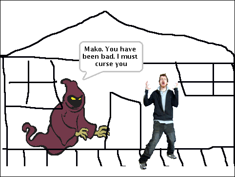
 A few years ago, I ran into my friend


 But although I've spent quite a bit of time studying the Scratch
community in the last few years as it is grown to include millions of
participants and projects, I forgot about about Jay's photo shoot.
A couple months ago,
 That said, given the rather emotive nature of the pictures, I seem to
usually end up being
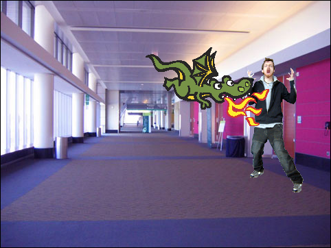 There's quite many more entertaining examples
 According to UDD, we had 506 packages to fix when we started and after todays update it has dropped to 485. It is a little less than the


 & another mix of various RC bug fixes: applying patches from others,
fixing stuff myself, closing obsolete bugs:
 Hi all!
My name is Alberto Garcia and this is my first (well,
 During the
 Two days ago, I finally brought my system up-to-date with regard to the GNOME packages that I use. I was very reluctant because I am using a heavily customized gnome-panel and I waited until
 Debian's

 So, like many people, I have received GNOME 3 in the latest upgrade on Debian testing, and switched away to Xfce very soon after. What's amazing (to me) about this whole experience, however, is how easy it is to switch desktop environments in Debian. Two years ago, I

 If you ever get an error message from the


